Continue to Site

Welcome to EDAboard.com

Welcome to our site! EDAboard.com is an international Electronics Discussion Forum focused on EDA software, circuits, schematics, books, theory, papers, asic, pld, 8051, DSP, Network, RF, Analog Design, PCB, Service Manuals... and a whole lot more! To participate you need to register. Registration is free. Click here to register now.

Easily variable active low-pass filter?

Status
Not open for further replies.

PgrAm

Newbie level 6
Joined
Jun 3, 2012
Messages
12
Helped
0
Reputation
0
Reaction score
0
Trophy points
1,281
Activity points
1,374
Hi,

I've been trying to design an active low pass filter that can have both the cutoff frequency and gain adjusted independently using single potentiometers. This is what I have come up with:
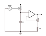
lowpass.png

Unfortunately there are several problems my design:

  • its essentially a passive filter which is then amplified
  • its non-inverting

Anyone know of an inverting circuit which can have gain and frequency easily adjusted by one potentiometer each?
 

Hmm that's an interesting idea although trasconductance op-amps don't seem to be as readily available as regular ones. Surely there must be a circuit that uses standard op-amps.
 

Anyone know of an inverting circuit which can have gain and frequency easily adjusted by one potentiometer each?

What about the classical first order active lowpass filter?
Circuit: R2||C2 in the feedback path (between output and inverting input); R1 between signal input and inv. opamp input node.
Gain: -R2/R1 with R1>>potentiometer
3-dB cutoff: 1/(R2C2) with R2>>potentiometer.
 

What about the classical first order active lowpass filter?
Circuit: R2||C2 in the feedback path (between output and inverting input); R1 between signal input and inv. opamp input node.
Gain: -R2/R1 with R1>>potentiometer
3-dB cutoff: 1/(R2C2) with R2>>potentiometer.

The problem with that circuit is that adjusting the value of R2 to modify the frequency will also alter the gain.
 

What about the classical first order active lowpass filter?
All first order filters are functionally equivalent (they have a real pole), so what should be the advantage of using a different topology than that shown in post #1?
 

All first order filters are functionally equivalent (they have a real pole), so what should be the advantage of using a different topology than that shown in post #1?

In the last line of post#1 the OP did ask for an inverting topology.
 

This circuit may be suitable.
- It's inverting.
- Input impedance is constant and resistive.
- Gain can be adjusted above or below unity.

It's still only first order, but could easily be adapted to second order. The OP didn't mention what order (s)he wants.


Hi,

Transconductance OpAmp are available in Farnell or RS components, you can get plenty of them. One interesting feature is that their bandwidth is much higher compared to the ordinary voltage feedback OpAmp. You can create easily adjustable low pass or high pass filters with them. If you need narrow band pass filter you need to use combination of low pass and high pass filter.

But I agree - they are not widely used and you need to learn how to work with them.

Kind regards,
Luben
 

Status
Not open for further replies.

Part and Inventory Search

Welcome to EDABoard.com

Sponsor

Back
Top