Continue to Site

Welcome to EDAboard.com

Welcome to our site! EDAboard.com is an international Electronics Discussion Forum focused on EDA software, circuits, schematics, books, theory, papers, asic, pld, 8051, DSP, Network, RF, Analog Design, PCB, Service Manuals... and a whole lot more! To participate you need to register. Registration is free. Click here to register now.

DSP schematic Design

Status
Not open for further replies.

Fikadu

Junior Member level 3
Joined
Feb 22, 2015
Messages
31
Helped
0
Reputation
0
Reaction score
0
Trophy points
6
Activity points
304
I have been using IT TMS30F28335 DSP to for different system controllers . All designed hardware was working good so far. Now, it is to develop a new hardware for different purpose. But , it prompts error when connecting Emulator/debugger/ for which a screenshot is attached herewith. For all hardware we designed so far, we used digital and analog ground for the DSP power supply connections and other electrical components as it is recommended in TMS32028x Design guideline. But , for the recent one, our hardware Engineer changes all to analog ground . could this be a reason for the error? is that mandator to use both analog and digital ground while designing TMS320F28335?


Thank you a lot
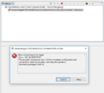
Emullator_Error.PNG
 

There are hundred reasons why the debugger can't connect, e.g. missing power supply, device hold in reset, netlist error. Analog and digital ground connection is more a question of optimizing analog noise rejection. Shouldn't affect the digital section as long as all required ground connections are actually present.

Start the basic work, check supply voltages, clock oscillator is operating, debug interface wired correctly etc.


FvM, thank you a lot for your support.
I have checked a supply voltage at each checking points. All are as they are supposed to. A debug interface is also exactly the same with what I have been using for other properly working hardware. But, the DSP external Oscillator is not oscillating the correct frequency. I guess this is because the DSP is not working properly. what do you think about it?


Thank you
 

All components (IC, oscillator, etc.) need ground return paths for signals travelling between them.

If you have signals at positive and negative polarity then your devices ought to have both positive and negative power supplies.
 

Status
Not open for further replies.

Similar threads

Part and Inventory Search

Welcome to EDABoard.com

Sponsor

Back
Top