Continue to Site

Welcome to EDAboard.com

Welcome to our site! EDAboard.com is an international Electronics Discussion Forum focused on EDA software, circuits, schematics, books, theory, papers, asic, pld, 8051, DSP, Network, RF, Analog Design, PCB, Service Manuals... and a whole lot more! To participate you need to register. Registration is free. Click here to register now.

DRV10983 not giving 5V

Status
Not open for further replies.

ismu

Full Member level 2
Joined
May 12, 2009
Messages
145
Helped
1
Reputation
2
Reaction score
1
Trophy points
1,298
Location
nil
Activity points
2,340
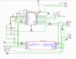
Am using DRV10983 BLDC driver chip from TI . when i used new chip which is giving 5V as output but when i connect PIC16F676 on this 5V buck line voltage is dripping .
am havin one more chip which was already used in working product which is giving 5V and can able to connect PIC16F676 . Do i need to program internal EEPROM of DRV chip to get proper 5V out put first ? please help me what to do on these newly order chip to make up.

2- Is there any cheapest solution for connecting this DRV chip with TI PC application otherthan USB to Any hardware board ,(this is more expensive )
 

Hi,

show the complete DRV10983 schematic (yours, not the datsheet one) and your PCB layout.
And give details where you measure and what current your load draws.

Klaus
 

    ismu

    Points: 2
    Helpful Answer Positive Rating
Hi,

show the complete DRV10983 schematic (yours, not the datsheet one) and your PCB layout.
And give details where you measure and what current your load draws.

Klaus

Please see the attached pic ,, i didnt do any internal EEPROM confiugartion . my plan was to configure DRV EEPROM with PIC16F676 through I2C but PIC16F chip is not loading and voltage is driping when i connect PIC chip ... same circuit is working with my old DRV10983 chip (which was already configured EEPROM with some other setup , i am not ure how they did) and this chip i working with same circuit and i can able to read and write those EPROM mem thrpough the same PIC16F chip and which is providing enough voltage 5V to that PIC16F chip .
 

Attachments

  • Capture.PNG
    Capture.PNG
    57.8 KB · Views: 149

Hi,

You did provide just the schematic, but no PCB layout and no load current informations, no measurement information.
I can't help without the informations.
Did you read my post?
Did you read the datasheet...thoroughly?

I did some reading for you.
Datasheet says the output voltage depends on VRegsel. VRegsel is "1" per default, this means 3.3V output.

Your PIC should be able to work with 3.3V. But it will need capacitors at the XTAL.

Klaus
 

    ismu

    Points: 2
    Helpful Answer Positive Rating
Hi,

You did provide just the schematic, but no PCB layout and no load current informations, no measurement information.
I can't help without the informations.
Did you read my post?
Did you read the datasheet...thoroughly?

I did some reading for you.
Datasheet says the output voltage depends on VRegsel. VRegsel is "1" per default, this means 3.3V output.

Your PIC should be able to work with 3.3V. But it will need capacitors at the XTAL.

Klaus
Thanks for your valuable information ... Attached PCB layout

load current is only for PIC16F chip + IR sensor (dont worry about load current becuase same circuit is supporting other old DRV chip which is already EERPOM programed )
if default voltage is 3.3V then i dont know why the DRV chip is gving 5V at 5V point intialy , wihtout PIC16 connection .
cappcitor at Xtel is optional i guess , becuase this circuit works fine for other DRV chip .
 

Attachments

  • Capture.PNG
    Capture.PNG
    59.7 KB · Views: 135

Hi,
load current is only for PIC16F chip + IR sensor (dont worry about load current becuase same circuit is supporting other old DRV chip which is already EERPOM programed )
I don´t worry ... but I read the datasheet..
VReg output voltage is specified at 50mA load. So if your application draws less than this, then the output voltage may rise.
--> for tests you should provide the same situation as given in the datasheet, otherwise expect deviations. How much? Nobody can tell.

Do you use the "Z" type or the "non Z" type DRV10983?

Are you sure you use ceramics capacitors?

What´s the exact L1 type/manufacturer?

What about the GND-plane and the thermal vias? (missing thermals won´t explain your discussed problem, but) increased GND impedance may cause spikes and malfunction at switching nodes. A buck is a switching circuit.

It seems your PIC_GND is routed from the P_GND pins through the buzzer....but PGND is expected to be the most dirtiest GND of your whole circuit.

capacitor at Xtel is optional i guess ,
I guess --> you design circuits "by guessing"?
Indeed I don´t think they´re optional. At least the PIC datasheet does not tell they are optional. Instead thy show a table with capacitor values.
But in detail they refer to the XTAL datasheet.

becuase this circuit works fine for other DRV chip .
My personal opinion: This is no argument. For me it sounds like "I don´t need to keep on red lights on that crossing, because there was no traffic for months now".
I surely believe that your design worked. But there are variations from chip to chip, variations in temperature and humidity, variations in supply voltage, aging..
In case your design is "on the edge" you risk random or long time failure.

I´m a designer for very reliable electronics, thus I strictly keep on datasheets. My circuits work for decades now 24/7. Very low failure rate.
You don´t need to do it like me. But you should be aware of the risk.

Klaus
 

    ismu

    Points: 2
    Helpful Answer Positive Rating
Hi,

I don´t worry ... but I read the datasheet..
VReg output voltage is specified at 50mA load. So if your application draws less than this, then the output voltage may rise.
--> for tests you should provide the same situation as given in the datasheet, otherwise expect deviations. How much? Nobody can tell.

Do you use the "Z" type or the "non Z" type DRV10983?

Are you sure you use ceramics capacitors?

What´s the exact L1 type/manufacturer?

What about the GND-plane and the thermal vias? (missing thermals won´t explain your discussed problem, but) increased GND impedance may cause spikes and malfunction at switching nodes. A buck is a switching circuit.

It seems your PIC_GND is routed from the P_GND pins through the buzzer....but PGND is expected to be the most dirtiest GND of your whole circuit.


I guess --> you design circuits "by guessing"?
Indeed I don´t think they´re optional. At least the PIC datasheet does not tell they are optional. Instead thy show a table with capacitor values.
But in detail they refer to the XTAL datasheet.


My personal opinion: This is no argument. For me it sounds like "I don´t need to keep on red lights on that crossing, because there was no traffic for months now".
I surely believe that your design worked. But there are variations from chip to chip, variations in temperature and humidity, variations in supply voltage, aging..
In case your design is "on the edge" you risk random or long time failure.

I´m a designer for very reliable electronics, thus I strictly keep on datasheets. My circuits work for decades now 24/7. Very low failure rate.
You don´t need to do it like me. But you should be aware of the risk.

Klaus
thanks for your valuable information , i will go through the points what you suggested .
 

Hi,

I don´t worry ... but I read the datasheet..
VReg output voltage is specified at 50mA load. So if your application draws less than this, then the output voltage may rise.
--> for tests you should provide the same situation as given in the datasheet, otherwise expect deviations. How much? Nobody can tell.

Do you use the "Z" type or the "non Z" type DRV10983?

Are you sure you use ceramics capacitors?

What´s the exact L1 type/manufacturer?

What about the GND-plane and the thermal vias? (missing thermals won´t explain your discussed problem, but) increased GND impedance may cause spikes and malfunction at switching nodes. A buck is a switching circuit.

It seems your PIC_GND is routed from the P_GND pins through the buzzer....but PGND is expected to be the most dirtiest GND of your whole circuit.


I guess --> you design circuits "by guessing"?
Indeed I don´t think they´re optional. At least the PIC datasheet does not tell they are optional. Instead thy show a table with capacitor values.
But in detail they refer to the XTAL datasheet.


My personal opinion: This is no argument. For me it sounds like "I don´t need to keep on red lights on that crossing, because there was no traffic for months now".
I surely believe that your design worked. But there are variations from chip to chip, variations in temperature and humidity, variations in supply voltage, aging..
In case your design is "on the edge" you risk random or long time failure.

I´m a designer for very reliable electronics, thus I strictly keep on datasheets. My circuits work for decades now 24/7. Very low failure rate.
You don´t need to do it like me. But you should be aware of the risk.

Klaus

Hi Klaus

Now am getting 5V after putting right inductor what they suggested in datasheet , after thet the issue is now my I2C read action is not respoding properly ... when i do write it is giving proper ACK ,,, after that if read same register data back it is showing 00 and same time DATA line become fully at zero level (SDA is starinting completely zero when the I2C read command R/W=High ... after this eight bits are zero and after stop bit SDA is become grounded by DRV chip (when i remove connection from DRV chip that line become high , it imeans DRV is making SDA to fully ground .

Another point is i tried same set by replacing one more chip which waS There in orginal working board used for other [roject and that chip is responding properly ( i was trying to write 00 memmory to AA data and tried to read back ) please help me .....

2-- one more question is i used PIC controller as I2C master for writing .. is that mandatory to use USB2ANY ($120 cost) for I2C configuration as whta TI suggested ? do we have any cheapest solution ?
 

The main advantage of USB2ANY is that it's supported by TI evaluation tools.
 

    ismu

    Points: 2
    Helpful Answer Positive Rating
Status
Not open for further replies.

Similar threads

Part and Inventory Search

Welcome to EDABoard.com

Sponsor

Back
Top