Continue to Site

Welcome to EDAboard.com

Welcome to our site! EDAboard.com is an international Electronics Discussion Forum focused on EDA software, circuits, schematics, books, theory, papers, asic, pld, 8051, DSP, Network, RF, Analog Design, PCB, Service Manuals... and a whole lot more! To participate you need to register. Registration is free. Click here to register now.

Drum (piezo) to operate LEDs?

Status
Not open for further replies.

Marty Reid

Newbie level 4
Joined
Jul 29, 2015
Messages
5
Helped
0
Reputation
0
Reaction score
0
Trophy points
1
Activity points
49
I want to add LEDs to my electronic kick pedal (Roland KD9) that light up the rim in response to how hard the piezo pad is hit. The LED ring is 12-24V (car headlight type) but the drum pad highest output seems to be around 50mV with crude metering. I know little about electronics but hopefully some of you might help me understand how I could make a simple circuit to boost the drum pad output to operate the LEDs without affecting the signal going to the drum sound module?
 

You will want to specify the Voltage and current of the LEDs and power source available to amplify the signal. and drive the LED current to control brightness. 12-24V is a wide range. Do you mean 12~14V? Do they have electronics included for fixed power?
 

You need three separate functions :- A power supply to feed your circuit which includes the power for the LEDs, an amplifier which includes some processing, to give the right brightness and duration for the flashing LEDs. The processing would only be some resistors and capacitors, not neccessarily a microprocessor. And finally a "T" junction module that takes the output from the Roland and feeds some of its signal to your new amplifier while allowing the main signal to go where it normally goes. This should be robust so some one standing on or kicking it will not break it.
So once you have a specification for the LEDs, then we could help you with the design of the amplifier, which in turn will lead to the specification for the power supply.
Frank
 

Yes, the output current from a piezo that is hit is very low so a power amplifier will be needed for it to light LEDs.
Look at the thousands of circuits in Google Images for E-Drum Circuit.

The original pulse will probably have such a short duration (unless the piezo is on a vibrating item) that the LEDs will be powered for a moment but you will not see anything until the duration is stretched with the circuit.
 

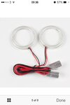
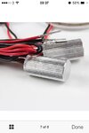
Thanks guys, some more info.. There is a small circuit on the front end of led ring as per pics, maybe voltage regulator? which would explain range of input voltage,
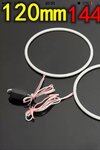
LED Quantity: 144 per ring
Outer Diameter: 120mm
Inner Diameter: 111mm
Wire Length: Approx.38cm
Operating Voltage: DC 12V~30V
Lumens : 21LM per chip
Power : 0.6W
Current : 0.45A

I was planning to power the amp circuit with 12VDC 700mA power supply, but have higher powered sources if needed.
I still don't have much info on the drum trigger output yet, but will look again. ThAnks
 

it looks like a constant current regulator and not dimmable

Plan B? show details in photo both sides? modify with cut & jumpers?

With suitable mods, we can drive it up to 1A peak since most of the events are burst anyways and not steady power, then we can use a sound level controlled resistance to control the current over a limited range.

I might suggest a PC type electret mic which is easy to amplify rectify and control the current levels, clamped to the rim.
**broken link removed**
 

Problem with using sound to activate is the LEDs will pick up on snare, guitar etc when playing. I should probably mention I play guitar while using 2 kick pedals (1 for snare, 1 for bass drum) and for performances I want each one to light up as it's played. Hence I want to use the pad trigger as an input if poss. Cheers
 

Hi Frank, does the below help? I really appreciate your input!
There is a small circuit on the front end of led ring, maybe voltage regulator? which would explain range of input voltage, but anyway I would assume 12vdc input.
LED Quantity: 144 per ring
Outer Diameter: 120mm
Inner Diameter: 111mm
Wire Length: Approx.38cm
Operating Voltage: DC 12V~30V
Lumens : 21LM per chip
Power : 0.6W
Current : 0.45A

I was planning to power the amp circuit with 12VDC 700mA power supply, but have higher powered sources if needed.
I still don't have much info on the drum trigger output yet, but will look again. ThAnks
 

This is not a good place to start from. LEDs as individuals run at 2 to 4V at a current between ,02 and 4 Amps. Your assembley has some electronics in it that converts 12 to 30V to what ever your LEDs consume., Also the power and current ratings do not make sense as .45 A X 12 V = 5.4 W, should that .6W really be 6 W?
The electronics could be either analogue or switching. The analogue method is to use a transistor to vary the output voltage by changing the voltage drop across its self, so if the REAL output is , say 9V, then with 12V in it drops 3 V and with 32V in it drops 23V. this system looses a lot of power and will require a heat sink.
The switching system, uses a switch to convert the incoming DC to AC and uses a transformer to get the correct output voltage, it is very efficient. It uses a lot more components but does not use a heatsink.
So which system do your LEDs use? or is there none, just a flakey specification.
Have you the tools and experience to construct this kit yourself?
Frank
 

https://obrazki.elektroda.pl/8595619000_1438327006.jpg image.jpg
Your right the power is stated as 6W sorry, my mistake. I've got tools for the basics. The rings haven't arrived yet but I've seen others on ebay with a heat sink like pics below. I guess I'll look in black front end box and measure the output to the ring when I put 12vdc into the box.

Photos of similar rings with heat sink on input
image.jpg
image.jpg
 
Last edited:

Hi,

it is just for optical effect?

For a good light effect I´d
* amplify the signal
* rectify it
* build a peak detector
* use a 20--100ms hold time
* use a decay with time constant of about 100..500ms
* instead of using the built in regulator i´d use a fixed voltage DC supply (wall wart) and an adjustable current source.
(too much effort?)

a lot of it could be built as software in a small microcontroller.

Klaus
 

Status
Not open for further replies.

Similar threads

Part and Inventory Search

Welcome to EDABoard.com

Sponsor

Back
Top