Welcome to our site! EDAboard.com is an international Electronics Discussion Forum focused on EDA software, circuits, schematics, books, theory, papers, asic, pld, 8051, DSP, Network, RF, Analog Design, PCB, Service Manuals... and a whole lot more! To participate you need to register. Registration is free. Click here to register now.
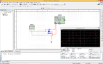
First i admit i am weak on basics.See the image, i am measuring the voltage across the diode.Actually it only passes positive wave,but it also passing negative value.what i misunderstood here.
bro you actually measured it across that source only, what you need to do is to place a resistor in series with that diode and then attach your probe parallel to that resistor .
I think you connect negative(GND) line at wrong place at XFG... connect it with (-) 3rd pin, and put a resistor between diode diode and XFG positive line.
In addition to what Usama said, I would add that what you are observing is the difference between a simulator and what would happen in the real world.
In your circuit, you show a diode connected directly across the output of a signal generator. The signal generator is apparently assumed to have zero output impedance, so it appears not to be bothered by being short-circuited by the diode for the positive half-cycles. In the real world, the signal generator has a certain output impedance, and the diode has a certain maximum forward current rating before it burns up. These two things fight against each other. The simulation shows the signal generator winning. In the real world, the diode might win, and the scope waveform might look clipped just the way you expected it. Or else maybe the signal generator would win and burn out the diode. In any case, you won't get the real world to behave exactly as that simulation shows.
Probe connection is not good... Connect +V probe in the cathode of that diode.. Before check the circuit diagram. You have done a half wave rectifier for no use because cathode is grounded. Right now diode will act as a Load...
This site uses cookies to help personalise content, tailor your experience and to keep you logged in if you register.
By continuing to use this site, you are consenting to our use of cookies.