Continue to Site

Welcome to EDAboard.com

Welcome to our site! EDAboard.com is an international Electronics Discussion Forum focused on EDA software, circuits, schematics, books, theory, papers, asic, pld, 8051, DSP, Network, RF, Analog Design, PCB, Service Manuals... and a whole lot more! To participate you need to register. Registration is free. Click here to register now.

digital volume control for speaker

Status
Not open for further replies.

preeti.kr

Newbie level 5
Joined
Mar 9, 2022
Messages
9
Helped
0
Reputation
0
Reaction score
0
Trophy points
1
Activity points
98
Hello all,
I have a analog potentiometer 100k which is used to control the volume of speaker. The flow is : Amplifier, volume control, speaker.
I am planning to convert this POTENTIOMETER Solution into digital .
But i m confused if any digital equivalent of potentiometer equivalent component is there ??
The potentiometer module in use is marked15 watt. Please share your comments if this is feasible.
 

Hi,

Why not the usual flow: pot --> amplifier --> speaker?
Your way is much more problematic regarding power dissipation, sound, part selection.

The easiest way is to control your existing power pot with a motor.

For sure you may use a couple of relays and power resistors. But for this you need to tell us how many steps you want and what step size (in dB) you want.

Klaus
 

15 W - 100k - audio potentiometer. The parameter combination makes absolutely no sense. Regular speaker impedance is in a few ohms range, even a 100 V PA system has maximal a few kohm, achieved by transformers.

Please give more information about speaker impedance and amplifier power.
 

The existing flow is amplifier --> pot --> speaker like this, so i m looking for alternate solution in this way.
Trying to get information of AMP and speaker.
The information i have till now is, they are doing the volume control of speaker, using volume control pot at the output of amplifier. for every speaker, one volume control pot is present.
 

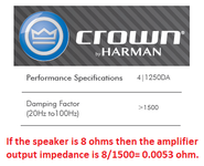
A speaker has a few resonances and sounds Boomy at the resonance frequencies when it is fed through a resistance. The output of an audio amplifier has an extremely low impedance (0.08 ohms or less) which damps the resonances.

Therefore a volume control should be at the input of the amplifier, not at the output.
Audio amplifiers have a spec called the damping factor. Here is an audio amplifier with a damping factor of >1500 then its output impedance is extremely low for good damping of the resonances of a speaker:
--- Updated ---

Sometimes an L-pad is used at each speaker. It has two variable resistors, look for it in Google.
 

Attachments

  • Crown amplifier damping factor.png
    Crown amplifier damping factor.png
    29.8 KB · Views: 160

The questions in post #4 (speaker impedance, power) aren't yet answered.

You surely won't use speaker potentiometer for HiFi sound systems, but for public address, e.g. broadcast speakers in hospitals or class rooms, it's not unusual. These system are also using higher voltage (e.g. 100 V) party lines and transformers to match individual speakers.
 

I also have to say: your description makes no sense. A 100K pot connected to a nominal 8 ohm speaker means that 99.9% of the range of your pot is useless.

Theres something missing here.
 

There are (or were) "digi-pot" ICs for baseband analog, there are digital
step attenuators for RF. Xicor I think made the digi-pot. Linearity will be
an issue at larger amplitudes perhaps. Click and pop suppression on
code-changes is a feature to look for it you're an audio purist or have
them for customers.
 

The amplifier has 5.1 channels, 130watt per channel. So since all 5 speakers will be connected to a common amplifier, how can we do volume control for any speaker individually.

**The POT Module consists of parallel arrangement of a big100k pot(shaft ), and one Fixed resistor of 100k(1/4watt) . So the total resistance is 50K.
 
Last edited:

The questions in post #4 (speaker impedance, power) aren't yet answered.

You surely won't use speaker potentiometer for HiFi sound systems, but for public address, e.g. broadcast speakers in hospitals or class rooms, it's not unusual. These system are also using higher voltage (e.g. 100 V) party lines and transformers to match individual speakers.
Yes, the application is similar to public addressing, not for HIFI sound systems. But the addition here is Individual Volume Control of Every Speaker.
 

Hi,

Still all this makes no sense.
Still we miss the speaker impedance.

A 5.1 system is an (HiFi) audio system. Often the 5.1 controller includes the individual volume control. Often already digitally controlled via I2C.

100k makes no sense. 100 Ohms makes more sense. Are you sure about the "k"?

As already written volume control at the (130W) amplifier output makes no sense. It kills sound quality and it generates a lot of heat.

What is it good for?
Why not control the amplifier input?
Please post some photos and sketches.
Give more details.

Klaus
 

A 5.1 amplifier drives 6 completely different channels: Left front, right front, center front, left rear, right rear and sub-woofer. The amplifier's input has its volume control for a good balance of the volume of all 6 channels.
 

The need of volume control here is, that the amplifier and all the speakers will be placed in different rooms. and to change volume of speaker, user will use the volume control at their room , instead of accessing the amplifier which is placed somewhere else, not in their room.
 

Hi,

While this eventually clarifies some things it still leaves some questions unanswered.
...and arises new questions.

So the amplifier is not used as 5.1 audio system, (I guess) it's used as 5 (6) channel amplifier.
You say speaker and amplifier is not in the same room ... thus I guess there may be multiple speakers per channel. Is this true?
Per channel:
If so: how many? How are they connected? What's the impedance?

I will come back when there is enough information for further discussion.

Klaus
 

The 5.1 amplifier probably has the 5 channels with highpass filters so that the low frequencies go to the sub-woofer. Then male voices will sound tinny like chipmunks.
The sub-woofer channel cannot be used in a room by itself because it probably has a lowpass filter making boomy and muffled sounds.
 

Typically these 5.1 amps do not have same power drive capability in each channel, a
spec pulled from a random one -

  • 【RMS Power Per Channel at 4 Ohm Driven, Total 250W】-- Main Channel RMS Power 40Wx2, Center Surround RMS Power: 30Wx3, Subwoofer Output Power: 80W.


Regards, Dana.
 

This thread is nonsense. 130 watt per channel amp, 15 watt potentiometer? 115 watts magically disappear?? OP, you need to restate your question and provide some useful information.
 

The need of volume control here is, that the amplifier and all the speakers will be placed in different rooms. and to change volume of speaker, user will use the volume control at their room

The usual method is an L-pad (mentioned in post #5 by Audioguru).
Price $10-20 each. You need one for each speaker.

There is need to consider the overall ohms seen by the amplifier output. Too many speakers in parallel might try to draw too much current from the amplifier. Consider whether you might arrange some speakers in series.

The L-pad might be a plain voltage divider using a variable resistor (potentiometer) made of robust resistive wire (such as nichrome).

Or it might be ganged potentiometers such as this L-pad schematic grabbed from internet:

L-pad sample schematic.png
 

Status
Not open for further replies.

Part and Inventory Search

Welcome to EDABoard.com

Sponsor

Back
Top