Continue to Site

Welcome to EDAboard.com

Welcome to our site! EDAboard.com is an international Electronics Discussion Forum focused on EDA software, circuits, schematics, books, theory, papers, asic, pld, 8051, DSP, Network, RF, Analog Design, PCB, Service Manuals... and a whole lot more! To participate you need to register. Registration is free. Click here to register now.

Digital storage oscilloscope in power electronics

Status
Not open for further replies.

abhishek.2138

Full Member level 2
Joined
Dec 21, 2013
Messages
133
Helped
0
Reputation
0
Reaction score
1
Trophy points
1,298
Activity points
2,378
I am working on 1 Kw AC drive project. The single phase AC motor speed is controlled by driving it through IGBT full bridge. Now, for designing the circuit some measurements are needed by Digital storage oscilloscope. The ground of DSO is connected to earth. The earth & neutral are short at the circuit breaker. When I connect this DSO ground in my circuit the fuse gets blown.

When I disconnect the earth connection to DSO the fuse doesn't blow, but the DSO probe has AC voltage shown by tester.

What should be done to avoid AC voltage at DSO probe???

Should I connect Isolation transformer at the DSO input (only phase & neutral of transformer secondary to DSO) & earth to be connected separately to DSO??

Please help...
 

If you have a two channel digital oscilloscope, you use both probes (witout connecting the ground side) and then use the A + B function after inverting one channel.

You will then see the DIFFERENCE between whatever is between the two probes.

If the waveform is still noisy, you can possibly try the averaging function of many readings which should average out the noise..
 

Why the fuse is blowing when you connecting DSO to your circuit ?

Because DSO ground is connected to earth ground through three pin power cable (L,N,E). you are directly shorting 400VDC to earth ground through DSO ground.
So you should isolate the DSO with isolation transformer
Or
DSO probe should be isolated with precision 1:1 ratio voltage transformer. You can select the voltage transformer with respect to your expected waveform.
 
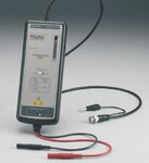
Best solution is to use a differential probe as shown in the attachment. Isolation transformer is possible, but dangerous because the oscilloscope case, connectors, controls carry live voltage.
 

Attachments

  • probe.jpg
    probe.jpg
    18.8 KB · Views: 126
Why the fuse is blowing when you connecting DSO to your circuit ?

Because DSO ground is connected to earth ground through three pin power cable (L,N,E). you are directly shorting 400VDC to earth ground through DSO ground.
So you should isolate the DSO with isolation transformer
Or
DSO probe should be isolated with precision 1:1 ratio voltage transformer. You can select the voltage transformer with respect to your expected waveform.

If I use isolation transformer, it will isolate phase-neutral from mains supply but again where to connect the earth point of DSO??

I think differential probes are better solution.
 

You need to ground the oscilloscope frame, for safety reasons, which means one side of your probes will also be grounded.

That leaves you with few choices.

The quick way is to just use two probes going into the two oscilloscope channels with the probe screens grounded. invert one channel, and use the A+B function.
You will then see the difference, or differential voltage between the the two channels displayed on a third channel.

If you have cash in your pocket, buy one of those fully floating isolated input differential probe as mentioned in post #4

One other solution might be to hire something more suitable for this particular project.


We are using GDS-1052U DSO of GWinstek. Its a two channel oscilloscope. I tried to use A+B function but I did not found such function. Is it possible to use A+B function on 2 channel oscilloscope??

If 1:1 isolation transformer is used with primary connected to AC mains & secondary connected to DSO and proper earthing is provided to DSO, will it be good alternative for differential voltage measurements??
 

Here is the user manual for the GDS 1000 series digital oscilloscope:
**broken link removed**

Scroll down to page 58 Maths functions.
The second function listed is the subtract function.
It will display the difference between channel 1 and channel 2 inputs.

Use two identical probes, and set both channels to the same sensitivity, and you should then be in business to see any signal that is the difference between the probe inputs.

Any common mode voltages or noise should be all but completely eliminated.

OK. But while measuring floating voltages where to connect the ground of the probe??
 

Both the oscilloscope frame and the frame of the device you are testing should both be at mains ground potential.

You can either clip your probes onto the frame, or leave them both off altogether. One may prove slightly noisier than the other, but it probably does not matter.
 

Both the oscilloscope frame and the frame of the device you are testing should both be at mains ground potential.

You can either clip your probes onto the frame, or leave them both off altogether. One may prove slightly noisier than the other, but it probably does not matter.


I measured floating voltage by difference between 2 channels. It shows the difference voltage but signal is noisy & there is less accuracy..
 

Yes there will be less accuracy, but with power electronics its probably just the wave shapes that are most important, (overshoot, ringing, rise times, etc) rather than extreme dc or amplitude accuracy.

Check to see if your digital oscilloscope has an averaging function, most do.
You can average repetitive waveforms over a great many sweep readings, and as noise is often random and asynchronous, it tends to average out back to zero, producing a much less noisy clearer waveform.
 

Status
Not open for further replies.

Similar threads

Part and Inventory Search

Welcome to EDABoard.com

Sponsor

Back
Top