Continue to Site

Welcome to EDAboard.com

Welcome to our site! EDAboard.com is an international Electronics Discussion Forum focused on EDA software, circuits, schematics, books, theory, papers, asic, pld, 8051, DSP, Network, RF, Analog Design, PCB, Service Manuals... and a whole lot more! To participate you need to register. Registration is free. Click here to register now.

Digital Circuit security project!

Status
Not open for further replies.

NorthZ

Newbie level 3
Joined
Sep 18, 2014
Messages
4
Helped
0
Reputation
0
Reaction score
0
Trophy points
1
Activity points
33
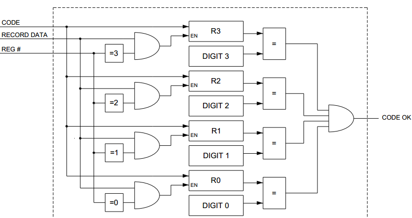
Hello! I'm trying to make a security project. It will work like this. The user enters a numeric code (four numbers) The machine will then compare that code to the code that is stored in his memory.
If the code match it will open the door for the user.

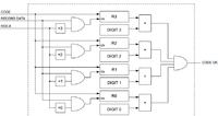
My circuit is currently like this!


And it works amazing with just one big flaw...
The "secret code" (Digit3 -> 0) is fixed. So my question is if anyone can help me write a similair circuit like mine, but that will have the opportunity for the owner to change the secret code!

(I hope everybody understand my circuit, Digit 3-> 0 is the secret code, R3 - R0 is the code the user enters. If you are unsure about anything please tell me!)

//Thank you!
 
Last edited:

Unable to see your picture on that link.

Why not just post your circuit and codes here?

Allen
 

Is there a reason why you can't use a simple microcontroller with EEPROM to store the code?

Turning it into a software solution makes the problem far simpler and you can make it store any code you like and change it if you want to.

Brian.
 

What device do you use as DIGIT 0-3?

Are the inputs in 4-bit binary to represent the password code?

Allen
 

Allen6502, to work it needs four lines for 'reg#' and another four for "code", the schematic is really a block diagram and each of the "=" blocks must itself be a digital comparator. This is why I suggested making a software solution although it isn't completely clear whether it is already and the posting is more figurative than a schematic.

Brian.
 

I hope you can see the picture now because i had some problems with it yesterday. But yea before i code i always make a circuit that works, I will also do that this time.
 

Allen6502, to work it needs four lines for 'reg#' and another four for "code", the schematic is really a block diagram and each of the "=" blocks must itself be a digital comparator. This is why I suggested making a software solution although it isn't completely clear whether it is already and the posting is more figurative than a schematic.

Brian.

Thanks, Now I can see how the circuit works.

If the circuit was already working with discrete logic components, R0-R3 are just 4-bit latches comparing with the preset bits stored in DIGIT_0 to DIGIT_3.

To change the application to use a mcu, all the gates would not be neccessary. And the design would be totally different. So I guess it is just a simple security circuit using just logic gates.

NorthZ said:
So my question is if anyone can help me write a similair circuit like mine, but that will have the opportunity for the owner to change the secret code!

You can use 4 pcs of 4-bit DIP switches or decimal Thumb switches in place of the "Digit 0 to digit 3". Then you'd be able to change the password by setting the DIP switches or turning the thumb switches.

Thumbswitch.jpg

Allen
 

Status
Not open for further replies.

Part and Inventory Search

Welcome to EDABoard.com

Sponsor

Back
Top