Continue to Site

Welcome to EDAboard.com

Welcome to our site! EDAboard.com is an international Electronics Discussion Forum focused on EDA software, circuits, schematics, books, theory, papers, asic, pld, 8051, DSP, Network, RF, Analog Design, PCB, Service Manuals... and a whole lot more! To participate you need to register. Registration is free. Click here to register now.

[General] different task performed at every push of one button

Status
Not open for further replies.
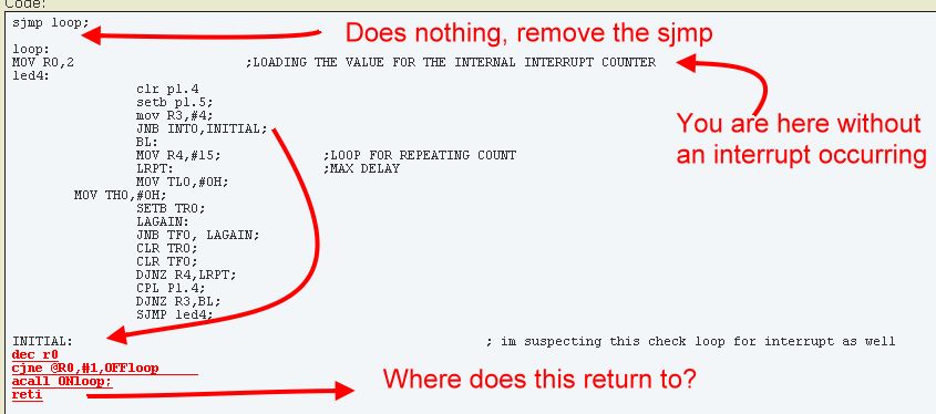
So think where the code goes back to after the 'reti'. It tries to resume form the address it saved when the interrupt occurred - but no address was saved so it jumps to a random address.

Brian.


hi Brian,

thank you for all the help and efforts to explain this to me. This might sound a very stupid question but i have to ask.
I always thought that when you call an interrupt it pushes the last address to the stack and after performing interrupt routine pops the previously saved instruction and excutes it. how do we tell the controller which address to jump at after "reti"? isnt it suppose to know by itself?
 

Hi,

You are wrong.

When an interrupt happens..
* the actual running instruction is performed
* then the address of the next instruction is safed on the stack
* (lower priority) interrupts are disabled
* then it jumps to the ISR and processes it
* with RETI it fetches the previously stored address from stack
* then it jumps to this address.
* it continues processing the code as usual

--> no instruction is pushed onto the stack, only address

RET and RETI are equal, except RETI (re) enables interrupts.

Klaus
 
  • Like
Reactions: hsa.a

    hsa.a

    Points: 2
    Helpful Answer Positive Rating
Code:
ORG 000H
SJMP CHECK;

org 003H;
	AJMP INITIAL
	
ORG 000BH;                     interrupt TIIMER routine
		ajmp timer
		
ORG 0030H
	CHECK:
MOV TMOD,#29H;                ;TR1 M2 / TM0-CT0 M1   
MOV IE,#10000011B; 
MOV TH1,#0FDH;	              ;9600BAUD RATE, ,8-BIT,1-STOP BIT;;;;;;;;;;;;;;
MOV SCON,#50H                 ;01010000b
SETB TI;                      ; TRANSMIT BIT HIGH, TRANSMITS WHEN LOW
setb TR1;

MS:DB 13,10,"ON",10,13,0
MS1:DB 13,10,"OFF",10,13,0

sjmp loop;

loop:        
MOV R0,2                      ;LOADING THE VALUE FOR THE INTERNAL INTERRUPT COUNTER
led4:
		clr p1.4
		setb p1.5;
		mov R3,#4;
		JNB INT0,INITIAL;
		BL:
		MOV R4,#15;             ;LOOP FOR REPEATING COUNT
		LRPT:                   ;MAX DELAY
		MOV TL0,#0H;
        MOV TH0,#0H;
		SETB TR0;
		LAGAIN: 
		JNB TF0, LAGAIN;
		CLR TR0;
		CLR TF0;
		DJNZ R4,LRPT;
		CPL P1.4;
		DJNZ R3,BL;
		SJMP led4;

INITIAL:                                                     ; im suspecting this check loop for interrupt as well
[COLOR="#FF0000"][U][B]dec r0
cjne @R0,#1,OFFloop     
acall ONloop;
reti[/B][/U][/COLOR]

ONloop:
ACALL DISPLAY1
		LOP:
		clr p1.5;
		setb p1.4
		mov R5,#4;
		BLINK:
		MOV R6,#30;              LOOP FOR REPEATING COUNT
		RPT:                   ;2 sec DELAY
		MOV TL0,#0H;
        MOV TH0,#0H;
		SETB TR0;
		AGAIN: 
		JNB TF0, AGAIN;
		CLR TR0;
		CLR TF0;
		DJNZ R6,RPT;
		CPL P1.5;
		DJNZ R5,BLINK;
		ret

TRANS:
MOV SBUF, A;
JNB TI,$
CLR TI
ret

OFFloop:
ACALL DISPLAY2
LOP2:
		clr p1.5;
		setb p1.4
		mov R5,#4;
		BLINK2:
		MOV R6,#30;              LOOP FOR REPEATING COUNT
		RPT2:                   ;2 sec DELAY
		MOV TL0,#0H;
        MOV TH0,#0H;
		SETB TR0;
		AGAIN2: 
		JNB TF0, AGAIN2;
		CLR TR0;
		CLR TF0;
		DJNZ R6,RPT2;
		CPL P1.5;
		DJNZ R5,BLINK2;
		RETI                                  ; interrupt routine doesnt return to the loop. it turns the led on constantly after blinking it 4 times

DISPLAY2:
CLR A
setb p1.4
MOV DPTR,#MS1;
MOV R2,4
dis1:
CLR A
MOVC A,@A+DPTR;
acall TRANS
INC DPTR;
DJNZ R2, dis1
ret
		
DISPLAY1:                   ;displays ON
setb p1.4
MOV DPTR,#MS;
MOV R7,2
dis:
CLR A
MOVC A,@A+DPTR;
acall TRANS
INC DPTR;
DJNZ R7, dis
ret

timer:
        PUSH ACC;
		SETB P1.4;
		SETB P1.5;
		POP ACC;
		RETI;

END


here is the code that i edited after understanding what you were trying to explain. the code isnt funtioning the way i want though but am i returing from my loops in the right fashion now?
 

Perhaps this helps:


Try to keep subroutines and ISRs isolated and make sure each finishes with ret or reti, if you jump from one to another you will quickly lose track of which address is on the stack to return to. In particular, if you use conditional jumps between them you will find it hard to follow the program flow under different conditions, it may work one time but not another.

Brian.
 
  • Like
Reactions: hsa.a

    hsa.a

    Points: 2
    Helpful Answer Positive Rating
the "reti" in the INITIAL loop should return to "BL" subloop

- - - Updated - - -

i have kept R0=2 outside the interrupt loop so that whenever one "ON" & one "OFF" loop is executed, the value of R0 is reset.
 

Hi,

But you used a JUMP (not a CALL) to enter INITIAL, therefore there is n return address on the stack.
Never enter a subroutine with a JUMP (unless you are experienced enough)

--> follow Brian´s recommendations.

My recommednation: draw a flow chart. Use different colors to mark ISRs, subroutines, main, main_loop.

Klaus
 
  • Like
Reactions: hsa.a

    hsa.a

    Points: 2
    Helpful Answer Positive Rating
Hi,

But you used a JUMP (not a CALL) to enter INITIAL, therefore there is n return address on the stack.
Never enter a subroutine with a JUMP (unless you are experienced enough)

Klaus

hey,
thanks it solved the loop issue. however, it is giving me the following response on hyperterminal when interrupt is pressed ten times;


OFF
¨Â
OF
OFF
¨”ҕ{0²|uŠuŒÒŒ0ýŒÜï²”Ûé"¶+y"Ñ•Ҕ}~uŠuŒÒŒ0ýŒÞﲕÝé"õ™0™ý™"Á•
Ò”}~
ON

ON
OFF
¨”ҕ{0²|uŠuŒÒŒ0ýŒÜï²”Ûé"¶+y"Ñ•Ҕ}~uŠuŒÒŒ0ýŒÞﲕÝé"õ™0™ý™"Á•
Ò”}~
OFF
¨”ҕ{0²|uŠuŒÒŒ0ýŒÜï²”Ûé"¶+y"Ñ•Ҕ}~uŠuŒÒŒ0ýŒÞﲕÝé"õ™0™ý™"Á•
Ò”}~
OFF
¨”ҕ{0²|uŠuŒÒŒ0ýŒÜï²”Ûé"¶+y"Ñ•Ҕ}~uŠuŒÒŒ0ýŒÞﲕÝé"õ™0™ý™"Á•
Ò”}~
OFF
¨”ҕ{0²|uŠuŒÒŒ0ýŒÜï²”Ûé"¶+y"Ñ•Ҕ}~uŠuŒÒŒ0ýŒÞﲕÝé"õ™0™ý™"Á•
Ò”}~
Code:
ORG 000H
SJMP CHECK;

org 003H;
	Acall INITIAL;
	reti
ORG 000BH;                     interrupt TIIMER routine
		ajmp timer
		
ORG 0030H
CHECK:
MOV TMOD,#29H;                ;TR1 M2 / TM0-CT0 M1   
MOV IE,#10000011B; 
MOV TH1,#0FDH;	              ;9600BAUD RATE, ,8-BIT,1-STOP BIT;;;;;;;;;;;;;;
MOV SCON,#50H                 ;01010000b
SETB TI;                      ; TRANSMIT BIT HIGH, TRANSMITS WHEN LOW
setb TR1;

MS:DB 13,10,"ON",10,13,0
MS1:DB 13,10,"OFF",10,13,0

loop:        
MOV R0,2                      ;LOADING THE VALUE FOR THE INTERNAL INTERRUPT COUNTER
led4:
		clr p1.4
		setb p1.5;
		mov R3,#4;
		JNB INT0,INITIAL;
		BL:
		MOV R4,#15;             ;LOOP FOR REPEATING COUNT
		LRPT:                   ;MAX DELAY
		MOV TL0,#0H;
        MOV TH0,#0H;
		SETB TR0;
		LAGAIN: 
		JNB TF0, LAGAIN;
		CLR TR0;
		CLR TF0;
		DJNZ R4,LRPT;
		CPL P1.4;
		DJNZ R3,BL;
		ret;

INITIAL:                  
dec r0
cjne @R0,#1,OFFloop     
acall ONloop;
ret

ONloop:
ACALL DISPLAY1
		LOP:
		clr p1.5;
		setb p1.4
		mov R5,#4;
		BLINK:
		MOV R6,#30;              LOOP FOR REPEATING COUNT
		RPT:                   ;2 sec DELAY
		MOV TL0,#0H;
        MOV TH0,#0H;
		SETB TR0;
		AGAIN: 
		JNB TF0, AGAIN;
		CLR TR0;
		CLR TF0;
		DJNZ R6,RPT;
		CPL P1.5;
		DJNZ R5,BLINK;
		ret

TRANS:
MOV SBUF, A;
JNB TI,$
CLR TI
ret

OFFloop:
ACALL DISPLAY2
LOP2:
		clr p1.5;
		setb p1.4
		mov R5,#4;
		BLINK2:
		MOV R6,#30;              LOOP FOR REPEATING COUNT
		RPT2:                   ;2 sec DELAY
		MOV TL0,#0H;
        MOV TH0,#0H;
		SETB TR0;
		AGAIN2: 
		JNB TF0, AGAIN2;
		CLR TR0;
		CLR TF0;
		DJNZ R6,RPT2;
		CPL P1.5;
		DJNZ R5,BLINK2;
		RETI                                  ; interrupt routine doesnt return to the loop. it turns the led on constantly after blinking it 4 times

DISPLAY2:
CLR A
setb p1.4
MOV DPTR,#MS1;
MOV R2,4
dis1:
CLR A
MOVC A,@A+DPTR;
acall TRANS
INC DPTR;
DJNZ R2, dis1
ret
		
DISPLAY1:                   ;displays ON
setb p1.4
MOV DPTR,#MS;
MOV R7,2
dis:
CLR A
MOVC A,@A+DPTR;
acall TRANS
INC DPTR;
DJNZ R7, dis
ret

timer:
        PUSH ACC;
		SETB P1.4;
		SETB P1.5;
		POP ACC;
		RETI;

END
 

Hi,

A hint:
I assume your editor has a search function. Search on "ret". It will show all RET and RETI. Decide on every single item if it is correct.

Still missing the fow chart.

Klaus
 
  • Like
Reactions: hsa.a

    hsa.a

    Points: 2
    Helpful Answer Positive Rating
Time to show us the flow chart as Klaus suggests.

The jump into an ISR is still there.
Another point which may be relevant but I'm not sure which assembler you are using:
the "MS" and "MS1" look to be a table of bytes for your messages but they are placed as part of your code. "MS" for example is this sequence of bytes:0d,0a,4f,4e,0a,0d
which decodes to these instructions:
inc R5
inc R2
orl A,R7
orl A,R6
inc R2
inc R5

I bet you didn't know it was executing those instructions!
Move messages to the start of your code then jump over them or make sure the instruction flow bypasses them. Either way, may sure they are not 'in line' with the flow of instructions because the MCU can't tell what is a instruction and what is data, they are just numbers.

Incidentally, for text messages the standard way of storing them is to add a zero at the end as you have done but to check for the zero as the characters are read so you know when it ends. It's a safer method than counting the number of characters in a loop and it lets you change the messages without having to recalculate the length again.

Brian.
 
  • Like
Reactions: hsa.a

    hsa.a

    Points: 2
    Helpful Answer Positive Rating
My suggestion is again if possible go to high level language. Because it is so difficult to find the issues in assembly language and will be spending too much of time debugging the issue. In case it is mandatory to write in assembly the other option is if you know C you can program in C and the tools will convert to assembly language. If any minor modifications are required you can very well do it. It is my opinion only.
 

Hi,

If you have problems to study assembly you will have problems with any other language.
I don't want to say that assembly is more simple than other language...

But each language needs to be studied. Reading books. They all have rules you need to follow.
And if in post#27 at the end of "OFFloop" still is a RETI instead of RET...although it has been discussed many times...it's not a problem of assembly.

You need to learn basics. Independent of language. A flow chart. A concept. You need to know what you want to do in main loop or in ISR. You need to learn to program a small piece of code. You need to learn to test and debug this little piece of code. The ... if it is running correctely..then program the next little piece of code.

Don't get me wrong. I don't want to discourage you from writing code. No, I want to say you should keep going. But in smaller steps. And with the help of good books and the use of good example code. Nobody has learned a language within a couple of weeks, it us a hard way.

Klaus
 

Hi,

A hint:
I assume your editor has a search function. Search on "ret". It will show all RET and RETI. Decide on every single item if it is correct.

Still missing the fow chart.

Klaus


there you go.
and thank you for guiding me. please do tell me some good books to learn assembly language.
flow chart.png

- - - Updated - - -

besides that, I know C language and have an idea of python as well. I have worked at Visual studio. However, my task is to do this using assembly language and I have always been weak at it, as computer architechture scares me since undergrade. I want to improve it.
So, i am grateful to Mr Brian and KlausST for helping me out here.
 

Can't help you with books I'm afraid, when I learned programming, paper had only just been invented!

Thank you for the flow chart, I have some questions which mightl help to simplify it:

1. take the 'ON' route, when you say 'blink LED at 2Hz" do you mean just one flash lasting 0.5 seconds or a continuous flash at that speed? Bear in mind the next stop along the flow says "Blink LED at 1Hz" so somewhere there has to be a gap or you get a single flash at 0.75 seconds!

2. the "OFF" route is similar but resets R0 along the way. Again, exactly what blink is needed?

The software is yours of course but I would do it a slightly different way like this: (can't draw a flow chart at the moment)
Code:
start --> initialize the registers
loop:
wait for a signal to say the interrupt occurred --> go back to loop until you see it.
reset the signal so you are ready for the next interrupt
increment a counter
if the LSB of the counter is set, point to the address of "MS" otherwise point to the address of "MS1"
blink the LED
call a subroutine to send the message
jump back to loop:
Then make the ISR code like this:
Code:
set the signal to say there was an interrupt
reti
And the subroutine to send the message:
Code:
get the first character
sendloop:
if it is zero then return (ret)
wait until the UART is free to accept a character
pass the character to the UART
point to the next character
jump back to sendloop:

Brian.
 

Hi,

I can´t recomend a book.
But look at example codes: http://www.atmel.com/tools/8051REFERENCEDOCUMENTS.aspx

Well done so far.

You only showed one flow chart. This is for the main loop.
You need an extra one for each ISR. (I really don´t know how many you have..)

An ISR can never be in the same flow chart than the main loop, because it can happen (and will be processed) at any time.


***
To your code:
* use standard names and more meaningful names (it makes it easier for us to understand)
(main, main loop, ISR...)

For example: You could do some name modifications :
Instead of "CHECK" use "BEGIN"
"LOOP" is OK, but it is more obvious if you call it "MAIN_LOOP"
Instead of "timer" use "it_timer" or "ISR_timer" to make it obvious that this is the ISR.
Instead of "DISPLAY2" use "DISP_OFF"
Instead of "DISPLAY1" use "DISP_ON"
Instead of "MS" use "STR_ON" (STR for string, you could also use PTR for pointer)
Instead of "MS1" use "STR_OFF"
and so on

****
fchart1.PNG
Here you see that immediatley after each "Set 2Hz" there follows the "Set 1Hz" ... so how long do you think the "1Hz "is valid?

***
Divide your code in more visible sections and use comments. The REFERENCEDOCUMENTS show you how to.

Klaus
 
  • Like
Reactions: hsa.a

    hsa.a

    Points: 2
    Helpful Answer Positive Rating
Thank you for the flow chart, I have some questions which mightl help to simplify it:

1. take the 'ON' route, when you say 'blink LED at 2Hz" do you mean just one flash lasting 0.5 seconds or a continuous flash at that speed? Bear in mind the next stop along the flow says "Blink LED at 1Hz" so somewhere there has to be a gap or you get a single flash at 0.75 seconds!Brian.

by 2 hz i mean that turn on and off time will be off 2sec. i am runinng this 4 times so altogether it takes 8 sec to execute the interrupt loop. the program should return back to blinking led1 after blinking the led2 at hz for as many cycles as i program it for

2. the "OFF" route is similar but resets R0 along the way. Again, exactly what blink is needed?
Brian.

same with the OFF loop. the only difference b/w ON & OFF loop is that ONloop prints "ON" & OFFloop prints "OFF"

- - - Updated - - -

Hi,

Here you see that immediately after each "Set 2Hz" there follows the "Set 1Hz" ... so how long do you think the "1Hz "is valid?

Klaus
Well, led1 blinks continuously until an interrupt is generated. it was, for this reason, I used "sjmp led4" command

- - - Updated - - -

flow chart 1.png

i didnt quite understand what you mean by making a seperate flow chart for ISR.

Also, after the 2nd LED is done blinking it should ret from the interrupt loop and run the loop to blink led1 at 1hz until the 2nd interrupt is received. this whole process should repeat again

- - - Updated - - -

By the way, I am using Keil uVision5 to compile the program for 89c2051.
 

Hi,

try to set up a timer for an interrupt every about 0.25s
Follow: Timer 1 Mode - Interrupt method
https://exploreembedded.com/wiki/5.8051_Timer_programming

Use one variable/register "LED_mode":
0 = LED OFF
1 = LED blink 1Hz
2 = LED blink 2Hz

***
ISR: (pseudocode)
If LED_mode = 0 then switch OFF LED
if LED_mode = 1 then use a counter/flag and toggle LED every second interrupt
If LED_mode = 2 then toggle LED (every interrupt)
reset interrupt flags
RETI

Klaus
 
  • Like
Reactions: hsa.a

    hsa.a

    Points: 2
    Helpful Answer Positive Rating
Code:
ORG 000H
SJMP CHECK;

org 003H;
	Acall INITIAL;
	reti
ORG 000BH;                     interrupt TIIMER routine
		ajmp timer
		
ORG 0030H
CHECK:
MOV TMOD,#29H;                ;TR1 M2 / TM0-CT0 M1   
MOV IE,#10000011B; 
MOV TH1,#0FDH;	              ;9600BAUD RATE, ,8-BIT,1-STOP BIT;;;;;;;;;;;;;;
MOV SCON,#50H                 ;01010000b
SETB TI;                      ; TRANSMIT BIT HIGH, TRANSMITS WHEN LOW
setb TR1;

MS:DB 13,10,"ON",10,13,0
MS1:DB 13,10,"OFF",10,13,0

loop:        
MOV R0,2                      ;LOADING THE VALUE FOR THE INTERNAL INTERRUPT COUNTER
led4:
		clr p1.4
		setb p1.5;
		mov R3,#4;
		JNB INT0,INITIAL;
		BL:
		MOV R4,#15;             ;LOOP FOR REPEATING COUNT
		LRPT:                   ;MAX DELAY
		MOV TL0,#0H;
        MOV TH0,#0H;
		SETB TR0;
		LAGAIN: 
		JNB TF0, LAGAIN;
		CLR TR0;
		CLR TF0;
		DJNZ R4,LRPT;
		CPL P1.4;
		DJNZ R3,BL;
		ret;

INITIAL:                  
dec R0
cjne @R0,#1,ONloop     
acall OFFloop;
ret

ONloop:
ACALL DISPLAY_ON
		LOP:
		clr p1.5;
		setb p1.4
		mov R5,#4;
		BLINK:
		MOV R6,#30;              LOOP FOR REPEATING COUNT
		RPT:                   ;2 sec DELAY
		MOV TL0,#0H;
        MOV TH0,#0H;
		SETB TR0;
		AGAIN: 
		JNB TF0, AGAIN;
		CLR TR0;
		CLR TF0;
		DJNZ R6,RPT;
		CPL P1.5;
		DJNZ R5,BLINK;
		retI

TRANS:
MOV SBUF, A;
JNB TI,$
CLR TI
ret

OFFloop:
ACALL DISPLAY_OFF
LOP2:
		clr p1.5;
		setb p1.4
		mov R5,#4;
		BLINK2:
		MOV R6,#30;              LOOP FOR REPEATING COUNT
		RPT2:                   ;2 sec DELAY
		MOV TL0,#0H;
        MOV TH0,#0H;
		SETB TR0;
		AGAIN2: 
		JNB TF0, AGAIN2;
		CLR TR0;
		CLR TF0;
		DJNZ R6,RPT2;
		CPL P1.5;
		DJNZ R5,BLINK2;
		RET                           ; interrupt routine doesnt return to the loop. it turns the led on constantly after blinking it 4 times

DISPLAY_OFF:
setb p1.4
MOV DPTR,#MS1;
MOV R2,4
dis1:
CLR A
MOVC A,@A+DPTR;
acall TRANS
INC DPTR;
DJNZ R2, dis1
ret
		
DISPLAY_ON:                   ;displays ON
setb p1.4
MOV DPTR,#MS;
MOV R7,2
dis:
CLR A
MOVC A,@A+DPTR;
acall TRANS
INC DPTR;
DJNZ R7, dis
ret

timer:
        PUSH ACC;
		SETB P1.4;
		SETB P1.5;
		POP ACC;
		RETI;

END
This code gives me the following response each time the button is pressed.
Mr KlausST, if i remove reti from the OFF loop it doesnt print as well as gets stuck in the interrupt i.e, it keeps the led2 on constantly.

ON

OFF
¨”ҕ{0²|uŠuŒÒŒ0ýŒÜï²”Ûé"¶¡"ЕҔ}~uŠuŒÒŒ0ýŒÞﲕÝé2õ™0™
 

Hi,

i didnt quite understand what you mean by making a seperate flow chart for ISR.

Flow chart of ISR of post#36
fchartISR.PNG

This is processed "in parallel" to main loop, therefore it needs its own flow chart.

Klaus

- - - Updated - - -

Added:

Your code of post#37 still has the same error that Brian mentioned in post#29.

--> correct this.

Klaus
 

im sorry i pasted a wrong code. this outpu is for the a modified code where i have placed both "MS" & "MS1" before the check loop and after ORG 0030H

- - - Updated - - -

i have brought both strings in my code at the end and thanfully i got rid of the garbage values.
 

by 2 hz i mean that turn on and off time will be off 2sec. i am runinng this 4 times so altogether it takes 8 sec to execute the interrupt loop.
I understand what you mean but you actually have it backwards... Hz is a measure of frequency, 1Hz means it happens once a second, 2Hz means twice a second so it takes half as long, not twice as long! 1Hz = 1 second, 2 Hz = 0.5 seconds so you actually want 1Hz and 0.5Hz to give 1 second blink and 2 second blinks.

It is worth learning how to use timer interrupts to generate delays, with a little practice you can make precise delays of almost any length and even make several delays with different start times and lengths that run simultaneously.

Brian.
 
  • Like
Reactions: hsa.a

    hsa.a

    Points: 2
    Helpful Answer Positive Rating
Status
Not open for further replies.

Similar threads

Part and Inventory Search

Welcome to EDABoard.com

Sponsor

Back
Top