Welcome to our site! EDAboard.com is an international Electronics Discussion Forum focused on EDA software, circuits, schematics, books, theory, papers, asic, pld, 8051, DSP, Network, RF, Analog Design, PCB, Service Manuals... and a whole lot more! To participate you need to register. Registration is free. Click here to register now.
Depends on your application. There are many unseen parameters to be considered.
For instance : If the application has Low Frequency circuits, FR-4 is most popular and less expensive. If the application requires ROHS environment regulation, Lead Free PCB etc.
So, choosing a right PCB material is very depended on desired and requested conditions.
For FR-4 dielectric, the major cost contributor is the total weight of Cu, so 1oz Cu is twice the cost of 0.5oz which is why, you don't see many 1oz internal layers.
But going to polyamide (Kapton) and PTFE (Rogers) are quantum jumps in the price for the dielectric. which is why you don't see a lot of high-layer boards in Teflon.
I just have a look at some typical stackups for standard PCBs. They have used 18 um (0,5 oz) on outer layers and 35 um (1 oz). Any reason for thinner copper layers on top and bottom. I guess a 10 mil trace can carry more current in inner thick layers compared to outer thin layers. Is that correct ?
Regarding the dielectric, we are working with standard PCB with typical heights 1.6 mm or 2.4 mm and they are not flex PCBs.
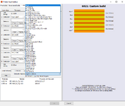
In the picture I shared in the first post. There are many FR4 dielectric in the list. What is the difference between high Tg, low Tg and mid Tg ? what is low CTEz and inorganic filters ? I would like to understand the consequences of these parameters while selecting the FR4.
Rogers is a name of the company or dielectric material ?
There is list of Rogers dielectric in the picture. Which one is better for high speed signals for example 10 Gbps Ethernet, USB 3.0 and PCI 3.0 in the design.
Steward mentioned Teflon, which dielectric in the picture have Teflon ?
Talk to PCB manufacturers you may use, they are the best to advise on the best options... Don't use Teflon unless you absolutely have to, and there are few designs that need it... It is a horrible material for PCB manufacture and puts the cost up dramatically...
Most internal power layers tend to start with 35um (1oz) copper, often these layers are used for heatsinking so far better than 18um, both for current and heat...
This site uses cookies to help personalise content, tailor your experience and to keep you logged in if you register.
By continuing to use this site, you are consenting to our use of cookies.