Continue to Site

Welcome to EDAboard.com

Welcome to our site! EDAboard.com is an international Electronics Discussion Forum focused on EDA software, circuits, schematics, books, theory, papers, asic, pld, 8051, DSP, Network, RF, Analog Design, PCB, Service Manuals... and a whole lot more! To participate you need to register. Registration is free. Click here to register now.

Did i botch this ADC circuit?

Status
Not open for further replies.

TXBDan

Junior Member level 1
Joined
Jul 30, 2013
Messages
16
Helped
0
Reputation
0
Reaction score
0
Trophy points
1
Activity points
156
Hi all,

I'm working on a project that requires 8 ADC channels and so am using a Microchip MCP3208.

The first four channels are measuring variably resistive loads (temp/pressure sensors) and so have an optional 5V pullup. I thought I would be clever and use an opamp buffer and an RC filter on each channel to provide a good low impedance source and some noise filtering. This is the circuit for one channel:

AnalogInCircuit.png

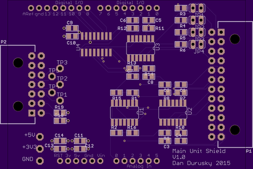
I spun a PCB with the design and am interfacing to an mbed microcontroller using the SPI interface. I'm using proven software libraries that should work.

The problem I'm seeing is that at random, some of the channels will start dropping voltage at the ADC input. The longer I let the device run the worse it gets. Sometimes all will seem normal for awhile, but then one or two channels will start to drop. The voltage at the ADC input will be pulled up to 5V, yet it can slowly drop to as low as 0.3V verified by multimeter.

So for some reason the ADC is pulling some current and I'm dropping voltage over the 2.2k RC resistor. I have a suspicion that my RC is bogging down the charge time of the ADC's capacitor and maybe things aren't ever charging and thus requiring constant current?

After doing more research, maybe my RC values are way too high.

Any input would be greatly appreciated.

(I'd also like to redesign this to use a 4.096V reference for both the ADC VREF and for the pullups, my 5V line is noisier than I anticipated.)

- - - Updated - - -

I should also add that SENS1_IN comes from the resistive sensor (sensor between SENS1_IN and GND) and SENS1 goes to the ADC input.
 
Last edited by a moderator:

hi,
What is the resistance range of the resistive sensor.?
It could be a self heating problem of the sensor.
E
 

In my testing so far, I have connected a basic 10k pot on a bread board (with 5V pull up enabled) as well as no connection relying on just the 5V pullup. In both cases I've sometimes seen it work exactly as expected and I've seen the voltage at the ADC input drop. I also have the last four channel inputs floating with no sensors and no pullups. I'm focusing on the four channels with inputs right now.

I can jumper GND, 3.3V, or 5V directly to the ADC input and in all cases it responds appropriately and I don't see signs of crosstalk between channels when I do this.

(the sensor used in application has a resistance range of 200ohms to 400kohms)

I'm getting mixed messages in my research on filtering for the ADC. There are plenty of websites/people saying a buffer into an RC into the ADC is great, and others saying that the RC impedance will slow down the ADC too much. Is this general architecture sensible?

Next time I will implement the filter in the opamp circuit as shown in the MCP3208 datasheet to avoid this I think.

Tonight I will remove the RCs and see what happens.
 

All ADC prefer a low impedance to drive them but the error you see doesn't suggest that is the problem. Anything that restricts current flowing into the ADC pin slows down the voltage change on it's internal sample and hold capacitor so it makes it less responsive to rapid changes. In that respect, the op-amp is a good thing because it ensures plenty of current is available to the ADC while not disturbing the voltage you are trying to measure.

I suspect your problem is one of three possibilities:
1. as suggested by Esp1, the sensor is self heating and the ADC is telling the truth.
2. the reference voltage is drifting, possibly due to your 5V regulator. Bear in mind the ADC value can change with as little as 0.0012V variation in supply.
3. you are not allowing long enough for the S&H to settle after changing channels.

You mentioning that four inputs are floating, that is a very bad idea, try grounding them and see if it stabilizes the channels you are using. If you are cycling through the input channels you could well be seeing residual voltage from the floating inputs being left on the S&H capacitor.

Brian.
 
  • Like
Reactions: TXBDan

    TXBDan

    Points: 2
    Helpful Answer Positive Rating
Thanks for the response.

I just home and began working on this. I first grounded the input for the last four channels. The first four channels are jumpered to 5V via the jumper shown in the schematic grab.

The RC filter on Channel 1 is removed and bypassed, straight shot from opamp to ADC. The rest of the channels are per the schematic above.

Here are my results:
ADCerr.JPG

Notes:
1. I measured the voltage directly at the ADC input and the displayed ADC value seems to represent the actual voltage.
2. These values drift over minutes. They tend to wander between 1300 and 4800ish. Channel 1 for example is now reading 4092 which is about right, but channel 2 is now at 697.
3. If i reset the microcontroller via reset button (not cycling power) the values don't change.
4. If i cycle power on the whole setup, the values start off where they last were (creepy...?)

I went through the code to drive the SPI bus and its pretty simple and straightforward. I ran the numbers w/ pencil and paper and i believe it to match the datasheet.

I have a for loop which reads over the 8 channels. I tried putting delays in the code between 50us and 50ms and the values remained similar. The function that reads the 8 channels is called at 10hz.

I also output the ADC values to the terminal just to make sure i don't have something dumb with my LCD output. They matched.

Is it possible that i damaged the opamps? I soldered them with a hot air gun, maybe i cooked them.

Any other ideas would be much appreciated! Thanks for your help so far.
 

Additional info:
Right now channel 2 is reading 699 which corresponds to the 0.89V i measure at the ADC input. Here is a trace through the circuit:

5.14V at the jumper and at the opamp positive input.
5.03V at the opamp output and negative input (feedback loop). (why are the two opamp inputs not the same?)
0.89V at the far side of the R-C junction and input to the ADC. (4.3V drop across the RC resistor...)

Which mean's the ADC is drawing 4.3/2200 = 2mA of current...

Hrmmm :/


Update:
Even more interesting info.

Channel 1 which has no RC filter is currently reading 1197 and measuring 1.3V at the ADC input. The opamp has 5.1V on its positive input and 1.3V on its negative input and output. How is the ADC pulling this down?

After about 2 minutes the value flips back to 4090ish and 5.1 at the ADC. Keeps going back and forth. I'm also reading only this one ADC channel now.
 
Last edited:

Firstly, I should point out that connecting the ADC inputs to the supply pin will never return a meaningful value because the measurement and reference will track together. Also be careful if you (wisely) use a precision voltage reference device because that sets the ceiling voltage you are allowed to feed into the inputs before exceedng the electrical specifications.

The ADC pin input current should be no more than about 1uA so the voltage drop across the R of the RC filter should drop almost nothing. The current has to be going somewhere
AFTER the resistor, in other words on the ADC side. To be honest I'm not sure what is wrong but my train of investigaton would follow this route:
1. check the reference pin is connected and really does have 5V on it. (noting the comment about Vin < Vref)
2. check you have not selected differential input mode.
3. check you are toggling the SPI clock fast enough as it is also used by the SAR. Too slow will let the S&H capacitor discharge.
4. check you are using a supply voltage >1.2V higher than Vref (ie 6.2V minimum) to the op-amp. Note section 4.1.3 of the MCP604 data sheet.

The last item might account for lower than expected readings but not the drop across the resistor.

Brian.
 
  • Like
Reactions: TXBDan

    TXBDan

    Points: 2
    Helpful Answer Positive Rating
Thanks again for your insight.

1. I will check this. I'm not using a precision reference as this circuit only has 5V input and I need to measure a potential 5V input with the ADC. (I'm starting to see why this won't work). I do have the ADC VDD and VREF tied to the same 5V supply.
2. I checked this last night and I believe I'm in Single Ended mode. I have not yet confirmed with a logic analyzer though. I do have a little USB one that I can use if need be.
3. I'm running the SPI clock at 1MHz which should be good. 2Mhz is max for the ADC with a 5V supply
4. Ah ha.. I'm definitely expecting a 5V output out of my opamp buffer while I'm powering the opamp rails with 5V.. I thought "rail to rail output" made this OK, but I just read the section you mentioned and see it is not. I do suspect the problem lies in the opamps as the ADC has always output exactly what's on its input pins.

I'm at work, but when I get home i'll post up the whole schematic for this thing. It looks like I have some good learning opportunities here. That's the fun part. :)

Thanks again!
 

You are communicating with someone here who just spent a week trying to persuade an admittedly complicated IC to initialize! Experience is a great teacher.

I learned never to trust a data sheet, even with a logic analyzer hooked up to it (it uses SPI to address it's internal registers) I couldn't see anything wrong. In fact I was doing everything correctly - the data sheet never mentioned a PLL in the chip had to synchronize to an incoming signal before it accepts programming data. I learned the hard way, make sure the signal is there first before writing to it!. Duh!!

Brian.
 
  • Like
Reactions: TXBDan

    TXBDan

    Points: 2
    Helpful Answer Positive Rating
Ok, here's the full scoop. This project is a digital dashboard/data logger for a car.

This circuit/PCB is an arduino form-factor shield that will plug into an Embedded Artists LPC4088 base board. It might be easiest to read my blog post on it here.

Basically I'm using the EA baseboard and using this custom "shield" to add ADC functionality as well as connector I/O. Here's a shot of the PCB:


The schematic is attached.

Here are the design goals/restrictions:
-5V and 3.3V power is available to the shield
-I need to be able to input a 0-5V signal
-The two Pulse Input channels are 12V from vehicle speed/tach sensors
-I'd like to keep the 8 ADC channels somewhat flexible as to not limit what type of sensors can go where, etc. Most sensors will either be variable resistors or a straight voltage 0-5V

Where I've gone wrong:
-As betwixt pointed out, I'm asking rail-to-rail input range of my opamps and they are not designed to do this. I maybe be able to find a drop in replacement. An LT1366 might be suitable as it claims rail-to-rail input and output capability.
-I know i don't have a nice VREF for the ADC. I only have 5V available and i need 0-5V input (unless i scale) so i didn't have much margin for regulating down. Maybe a 4.096V reference would work well for my resistive sensors, but i'd still have to scale down for the external 0-5V sensors.

Any thoughts? Thanks again!
 

Attachments

  • main_unit_shield.pdf
    27.1 KB · Views: 81

Looks very nice, is the PCB ground planed? I can't see the tracks to tell how the grounds are joined.

Brian.
 
  • Like
Reactions: TXBDan

    TXBDan

    Points: 2
    Helpful Answer Positive Rating
Thanks. Yep, GND and 5V are on planes. It's a four layer board.

Tonight if I have time I'll try putting GND and/or 3.3v into all the channels. This would be within spec for the opamps so should work, right? If not I have other issues.
 

I think that should work. The input is allowed to go slightly below ground and up to 1.2V below VDD so you should be OK with zero to 3.3V.

Brian.
 
  • Like
Reactions: TXBDan

    TXBDan

    Points: 2
    Helpful Answer Positive Rating
I tested again last night using only 0-3.3V inputs and something is still wrong. Some channels don't respond, some report wrong values, etc. Maybe I damaged the opamps. The ADC continues to work as expected if I drive its inputs directly.

I ordered new TI OPA4342 opamps which claim rail-to-rail input and output. You can even exceed the rails a bit on the inputs. I'll have those and a replacement ADC if necessary to try on Saturday.
 

To follow up, i finally got this working. I believe it was a combination of two things:

1. I was using opamps that didn't support rail-to-rail inputs, thanks betwixt. The TI OPA4342s are working well.

2. I had a short between a via and a resistor pad. Lesson learned: I need more space around vias when doing layouts.

3. I was getting a little overzealous with the hot air gun and frying things. I went through several opamps and ADCs, each iteration giving a new random problem. Finally i got more parts and hand soldered everything and voila, it worked. From now on i'll use the hot air for removing parts and possibly for discretes, but i'll keep to hand soldering ICs.

Thanks all!
 
Last edited:

Status
Not open for further replies.

Part and Inventory Search

Welcome to EDABoard.com

Sponsor

Back
Top