Continue to Site

Welcome to EDAboard.com

Welcome to our site! EDAboard.com is an international Electronics Discussion Forum focused on EDA software, circuits, schematics, books, theory, papers, asic, pld, 8051, DSP, Network, RF, Analog Design, PCB, Service Manuals... and a whole lot more! To participate you need to register. Registration is free. Click here to register now.

Determining Characteristic Impedance with T-line Circuit Model

Status
Not open for further replies.

celebrevida

Member level 2
Joined
Oct 25, 2016
Messages
47
Helped
0
Reputation
0
Reaction score
2
Trophy points
8
Activity points
524
Take a two port/four terminal transmission line. It can be modeled as a distributed series of this basic element:
Transmission_line_element.svg.png

The characteristic impedance is given by:
Z0 = sqrt((R+jwL)/(G+jwC))

But suppose I was given some black-box transmission line SPICE circuit model and only had access to the four terminals. How would I go about simulating it to determine its Z0?
 

The circuit is no realistic model of a lossy transmission line because the losses are frequency dependent (both skin effect and dielectric losses).

Z0 can be determined by measuring the input impedance of the terminated transmission line over a sufficient frequency range. You get input impedance ripple for Zo ≠ ZL, between Zo and Zo²/ZL.

Okay I understand the model is oversimplified. But let's say I had a realistic model but only had access to the four terminals. Let's call the input terminals A+/A- and the output terminals B+/B-

Okay so I will connect a ZL=50ohm across B+/B-. Likely Zo ≠ ZL. So if I put an AC source between A+/A- and sweep frequency and look at Z(jw)=V(jw)/I(jw) of this AC source, there is some kind of peaking on Z(jw) between Z0 and Z0^2/ZL.

So peak(Z(jw)) = Z0?

And if so, why? Sorry my T-line understanding is limited.
 

So peak(Z(jw)) = Z0?
It depends. The input impedance is ZL for l = n*λ/2. The other extremum occurs at odd multiples of λ/4, either larger or smaller than ZL, depending on Z0. I gave the relation in my previous post.
 

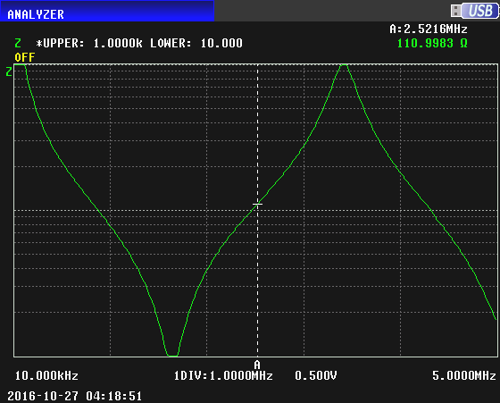
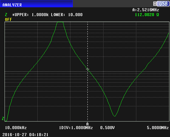
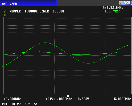
I have a roll of 100 feet of old-fashioned twisted pair telephone cable. I measured the impedance at one end with an impedance analyzer. The analyzer sweeps frequency from 10 kHz to 5 mHz; the frequency (horizontal) scale is linear rather than the more common logarithmic format. The measured impedance is shown on a vertical scale ranging from 10 ohms at the bottom to 1000 ohms at the top.

Here is the impedance with the other end of the cable open circuited:

6605544700_1477613658.png


Here is the impedance with the other end of the cable short circuited:

2317908700_1477613732.png


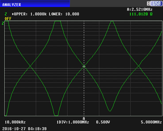
Here are the previous two curves superimposed. Where they cross is the characteristic impedance of the cable. There is a marker at that frequency, and in the upper right of the image can be seen the value of the impedance, which is 111 ohms.

3160006600_1477613900.png


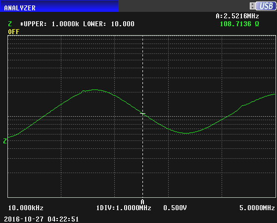
With a termination of 50 ohms, we get this impedance sweep:

3478363600_1477614331.png


Now with terminations of 50 and 100 ohms superimposed:

5395064100_1477614911.png


We can see that the 100 ohm termination results in an almost flat measured impedance. This means that the Zo is about 100 ohms. The earlier curves that intersected at 111 ohms gave a more accurate Zo.

These curves only show the magnitude of the measured Z; the true measured Z has a slight non-zero phase, but these curves are very close to the true Zo.

At any particular single frequency, the Zo of the cable can be found like this:

Measure the impedance at one end with the other end open; call this Zopen. Measure the impedance at one end with the other end shorted; call this Zshort. Zo is given by SQRT(Zopen*Zshort).

On the third image, at any frequency Zo is halfway between the curve for an open and the curve for a short. Of course, where the curves for open and short intersect shows Zo directly.
 
Last edited:

The Electrician: Thank you for your detailed plots and explanation!

I went ahead and tested it out:

Using this as my transmission line unit element:
View attachment 133095

Rdx=0.001, Ldx=0.07pH, Gdx=1/10M, Cdx=0.030fF
(Very small values were used so that my model can work at high frequencies)

I put several of these in series in my circuit. Then I performed AC sims one with open termination and one with shorted output termination and calculated z0_meas = sqrt(zopen*zshort)
I also plotted: z0_calc = sqrt((R+jwL)/(G+jwC))

The two plots of z0_meas and z0_calc match exactly! From 1Hz to 100MEG, I see z0=100. At that point it rolls off until around 100GHz, z0=48

So this answers my original question! Thank you so much!

So one last question. How would one derive the result Z0=sqrt(Zopen*Zshort) to begin with? I mean if one were to explain the theoretical or mathematical basis for this method and equation, what is a succinct way to explain it.
 

At any particular single frequency, the Zo of the cable can be found like this:

Measure the impedance at one end with the other end open; call this Zopen. Measure the impedance at one end with the other end shorted; call this Zshort. Zo is given by SQRT(Zopen*Zshort).
An ideal transmission line of length n*λ/4 gives Zshort and Zopen of zero and infinity or vice versa. The calculation fails at these frequencies.
 

An ideal transmission line of length n*λ/4 gives Zshort and Zopen of zero and infinity or vice versa. The calculation fails at these frequencies.


I said to "measure" the impedances with open and short at the other end. The calculation will not fail with "measured" impedances. :)

If one cared to apply it to ideal lines of those particular lengths, it might be necessary to use a calculation involving limits.
 

The input impedance of transmission line is given by Zo*(1 + Γ*exp(-2*γ*l))/(1 - Γ*exp(-2*γ*l)). Where Γ is the reflection coefficient at the load end, l is the length of the line and γ is the propagation constant. For short circuit Γ is -1 and open cicuit Γ is 1. Thus geometric mean of sqrt(Zshort*Zopen) is the characteristic impedance.
 

Status
Not open for further replies.

Part and Inventory Search

Welcome to EDABoard.com

Sponsor

Back
Top