Continue to Site

Welcome to EDAboard.com

Welcome to our site! EDAboard.com is an international Electronics Discussion Forum focused on EDA software, circuits, schematics, books, theory, papers, asic, pld, 8051, DSP, Network, RF, Analog Design, PCB, Service Manuals... and a whole lot more! To participate you need to register. Registration is free. Click here to register now.

Detection of push button press while driving LED

Status
Not open for further replies.

nicknh

Newbie level 2
Joined
Jan 10, 2011
Messages
2
Helped
0
Reputation
0
Reaction score
0
Trophy points
1,281
Activity points
1,299
Hi All,

switch.png

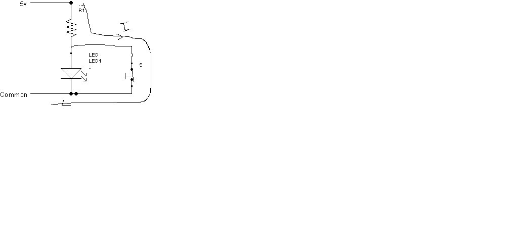
I have a circuit (see PNG above) that's going to be a wall mounted remote switch. I only have 2 low voltage wires running into this switch and I need to do two things.

1) I need to be able to turn the LED on/off (to indicate a state - on/off)...normally, this would be simple - I'd just apply +5V and the LED would light (or not apply and it would be off).

2) I need to detect if the push button switch also tied in parallel to the resistor/LED branch gets pushed closed...

Do any of you know of a basic circuit that could allow me to do both - drive the LED (either on or off) AND detect the push button's closed state - all using just the 2 wires?

Thanks,
Nick
 

Yes, You can read the key. Put a diode in reverse direction to the LED - when you change the polarity of the input you can read the key status (current/no current). Actualy you can read several keys by adding in serial to them different resistors.

See attached

Of course the reading of the button status is more complex - you need to change the polarity of the 2 wires which will require 2 uP pins.
 

Attachments

  • 2 WIRES KEY & LED.png
    2 WIRES KEY & LED.png
    13.7 KB · Views: 108
  • 2 WIRES SEVERAL KEY & LED.png
    2 WIRES SEVERAL KEY & LED.png
    20.7 KB · Views: 135

hi friends
I think you should implement x-or gate. when you provide supply led will glow but as you press the switch the led will off becos X-or gate has 0 o/p when both i/p are same (either 1,1 or 0,0).

the led will glow only when only one of two has high logic, thus you can perform both glowing the led and also check the status of switch.
 

Can you possibly draw out the schematic for what you mean here? Thanks!

---------- Post added at 11:49 ---------- Previous post was at 11:48 ----------

Thansk for the reply. My problem is that the switch that I'm using at a remote location can't be changed in terms of schematics. So, all I can do is local work...not on the remote switch (like adding in that diode).

Any additional thoughts?

Thanks!
 

ya you can if you place the switch in parallel with led. as long as you press switch the current will follow low impedence path means through resistor and switch not to led.

 
Last edited:

Status
Not open for further replies.

Similar threads

Part and Inventory Search

Welcome to EDABoard.com

Sponsor

Back
Top