Continue to Site

Welcome to EDAboard.com

Welcome to our site! EDAboard.com is an international Electronics Discussion Forum focused on EDA software, circuits, schematics, books, theory, papers, asic, pld, 8051, DSP, Network, RF, Analog Design, PCB, Service Manuals... and a whole lot more! To participate you need to register. Registration is free. Click here to register now.

Detecting presence of KNOWN frequency

Status
Not open for further replies.

kripacharya

Banned
Advanced Member level 4
Joined
Dec 28, 2012
Messages
1,204
Helped
182
Reputation
360
Reaction score
175
Trophy points
1,343
Location
New Delhi
Activity points
0
The signal is buried in all sorts of noise. Impulse, gaussian, bangalore-chatter, other high strength signals close by etc etc. But the frequency is precisely known - well, within 5% at worst. I'm talking about frequencies in the range of .. oh.. 100Khz to 200Khz. SNR is most likely negative.....

How can I detect presence/ absence (that's all I need) of the signal with a high degree of certainty ? Some sort of correlation algorithm ? Notch filters ? FFT .... ?? Direct conversion + sharp LPF ?
 
Last edited:

Hi,

maybe analog filters and tracking with pll.

Digital:
look for DFT.

Klaus
 

Hi,

maybe analog filters and tracking with pll.

Digital:
look for DFT.

Klaus

yeah, i've already listed those as possibles. But which would be great at doing what I need ?

One other method seems to be to use lock-in amplifiers, but I don't understand the theory so well... isn't this the same as a PLL with a narrow filter ?
 

I chose a biquad filter, when I wanted to detect a morse code signal coming over short wave. Often there would be another broadcast on a nearby frequency. I needed a selective audio filter tuned to a single audio pitch.

A state variable filter was another type I considered.

These filters are made from a few op amps, resistors, capacitors.

It worked great. I wanted a center frequency between 500 and 1000 Hz. My filter came out somewhere in that range. I could tune in a broadcast to that audio pitch, and my filter responded only to that pitch, and did not get confused by another broadcast a step higher or lower in pitch.

This type of filter cannot be easily tuned to different frequencies. I had to take the frequency I got. Since I wanted high Q, it is important to use matching resistors and capacitors. That was my priority.

You desire a range of 100Khz to 200Khz. This will depend on the specs of the op amp.
 

I chose a biquad filter, when I wanted to detect a morse code signal coming over short wave. Often there would be another broadcast on a nearby frequency. ...

so you used a DCR ? Or what ? Your filter would be great only if you were able to match the transmit freq precisely. How did you do that with a VFO ... i presume you had a VFO ?
 

so you used a DCR ? Or what ? Your filter would be great only if you were able to match the transmit freq precisely. How did you do that with a VFO ... i presume you had a VFO ?

My shortwave radio has an option called a beat frequency oscillator. It is needed to bring in morse code and SSB broadcasts. The Morse signals come through as an audio frequency. I can turn the BFO knob to make the pitch go up and down. That is what I used to adjust the pitch so it activated my biquad filter.

I made my biquad bandpass filter with fixed components. It does not operate in the kHz region, but at a single audio frequency. It is not possible to adjust the center frequency. To do this easily would require a ganged potentiometer.

Or it can be done the hard way, with three individual potentiometers. But then you must be careful to adjust all three very accurately, if you want to maintain a high Q factor.
 

An LC tank circuit makes the classic bandpass filter.

If you want maximum Q, then you must custom select values to go with a given resistance.

It might take some effort to find the proper size tunable coil or capacitor.


An LC tank circuit makes the classic bandpass filter.

If you want maximum Q, then you must custom select values to go with a given resistance.

It might take some effort to find the proper size tunable coil or capacitor.


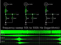
Actually it is well known that for a parallel RLC, the Q is R * root( C / L).
So in your simulations you see a sharper selectivity as C increases & L decreases.
 

Hi,
One other method seems to be to use lock-in amplifiers

I use lock in amplifiers when i
*generate a signal
* transmit the signal
* process it somehow (maybe a speedmeter with ultrasonic transducers)
* receive the processed signal
...
and want i know the amplitude and the phase delay of received signal referred to the original signal.

The difference to your application is, that i generate the frequency and use it´s phase information for the lock in amplifier.

I recommend DFT instead of lock in.
....
in my eyes it is very similar to DFT, but the DFT uses a sine and a cosine signal for correlation, but the lock in amplifier uses two 90 degree phase shifted square signals.

The benifit of the DFT is that you don´t need (but it is better) to have the original signal, the result is only the original frequency with very good calculatable filter bandwidth.
But it needs high speed ADC and a lot of processing power.

The benifit of the lock in is, that if you build it by hardware it is very simple (only some analog switches) and uncritical low pass filters. But result is the original frequency including
the overtones (according the square wave´s fourier series). It needs simple low frequency ADCs.

both are very precise and helpful instruments.

Klaus
 

Yes. The main trouble with trying to use lock-in amp is that I do not have the original ref signal. Best possible is a crystal derived "close" approx.

Next thought was doing DFT.

Then it occurred to me, radio receivers exist which have EXCELLENT selectivity, great sensitivity etc etc. A signal of less than 5uV snatched from the air with possible large interfering stations nearby. Why not use those principles ?

Bradtherad had much to do with this train of thought.

So after a night of dreaming about alternatives vs. what components I have on hand, I'm going to check out the following :

200Khz double-tuned BPF. Luckily I have some old TOKO transformers around which fit the bill !! With a low-impedance source and a JFET buffer I can get a gain of >20dB right there along with steepish band-pass filtering. Add some zeners/ transorbs/ diodes to limit impulse & other swamping signals

Add another tuned stage for selectivity & gain (~10dB) , followed by AGC amp which I already have with a dynamic range of 50dB.

Then use either a generic PLL (4046) or maybe an on-hand LM567 tone decoder - which is essentially a specialised/ simplified PLL.

That should give me great sensitivity ( ~ 10uV ) and good selectivity.
Lets see how it goes.
 

The total error frequency of Tx and Rx becomes the minimum BW of the Rx and thus limits the maximum SNR to capture the signal. A Type II mixer requires a much higher SNR than a Type I mixer . The capture range on Type I mixers shrinks with SNR below 20 dB, down to 10 dB but the problem is the VCO error becomes great that the capture range.

5% estimation error on the "Known " frequency may be far too high. VLF Navy transmitters have a known error frequency less than 1ppm which shifts during sunrise and sunset can still be hard to detect 1000 km away

An accurate SNR measurement must be made to determine the feasibility of any RX detector to determine Antenna signal requirements then RF gain and filtering to achieve desired Carrier to Noise Ratio (CNR) gain.

The choice of filtering, detector, PLL also depends on CNR, SNR, impulse noise ratio vs threshold of design method or discrimination between signal and noise is also critical. Also a definition is needed for permitted dropout duration and acquisition time.
 

Status
Not open for further replies.

Part and Inventory Search

Welcome to EDABoard.com

Sponsor

Back
Top