Continue to Site

Welcome to EDAboard.com

Welcome to our site! EDAboard.com is an international Electronics Discussion Forum focused on EDA software, circuits, schematics, books, theory, papers, asic, pld, 8051, DSP, Network, RF, Analog Design, PCB, Service Manuals... and a whole lot more! To participate you need to register. Registration is free. Click here to register now.

designing FM MODULATOR BY USING PLL but without using any IC or Chip.

Status
Not open for further replies.

LEARNING2

Newbie level 4
Newbie level 4
Joined
May 31, 2011
Messages
6
Helped
0
Reputation
0
Reaction score
0
Trophy points
1,281
Activity points
1,326
Hi everyone

I need to design FM MODULATOR BY USING PLL but without using any IC or Chip.
I need to build the circuit and examine it on the oscilloscope only.
thank you in advance for any help..
 
Last edited:

Maybe you can add modulate signal to the LooP filter's output , make sure that the bandwith of loop filter is less than one of modulate signal.
 
Hi everyone

I need to design FM MODULATOR BY USING PLL but without using any IC or Chip.
I need to build the circuit and examine it on the oscilloscope only.
thank you in advance for any help..

Carrier frequency?
Modulating signal... Sinusoidal? Maximum frequency?
Carrier deviation?

I think you agree on any answers for these main questions as long a simple circuit can be built and tested on a scope. :wink:
 
Maybe you can add modulate signal to the LooP filter's output , make sure that the bandwith of loop filter is less than one of modulate signal.

thanks for your help..But what i need is how to design pll for fm modulator without using any chip.

---------- Post added at 14:55 ---------- Previous post was at 14:51 ----------

Carrier frequency?
Modulating signal... Sinusoidal? Maximum frequency?
Carrier deviation?

I think you agree on any answers for these main questions as long a simple circuit can be built and tested on a scope. :wink:

yes u r right.. any values are accepted as long as it can be built and tested on oscilloscope.

waiting for ur response..
 

It's not clear, why you want to use a PLL. It's not necessarily needed for FM modulation. You basically need a kind of VCO, e.g. a LC oscillator with a varicap diode.

A PLL would require these additional components respectively building blocks:
- a reference oscillator
- a phase comparator
- a loop filter and amplifier
All these could be made without using ICs, but why?

thank you FvM for your reply..
I need to generate fm using pll it is a condition..
if you can help me with a primary circuit,i will then make the calculation..

thanks again.
 

Perhaps it is about Phase Modulation... This needs PLL.

Note:
In PLL and if the modulating signal is added to the low-pass filter output so that both drive the VCO input, the modulation index (VCO frequency deviation / modulating frequency) decreases with the modulating frequency for the same amplitude (acting as a high-pass filter).


Kerim
 
Last edited:
You are going to have a hard time making a PLL without using a PLL "chip"!

If you could use a PLL chip, you would choose one with an onboard charge pump. Then you could set up a passive loop filter with a narrow loop bandwidth (perhaps 2 KHz bandwidth) and connect that to the vco tuning port. Then you could also AC couple a modulating signal on the same VCO tune port. If you programmed the PLL chip to have a high divisor ratio (N=10,0000 for example) and locked the PLL to a low frequency clock, you would then have an FM modulated VCO phase locked to a clock.
 
You modulate the reference frequency to exactly track the modulation put on VCO as seen by the phase detector through dividers. It is called two port modulation and the objective is make the phase detector see no frequency shift due to modulation. If your PLL has to change the PLL frequency over a significant range the delta divider ratio in VCO path to phase detect will force the reference modulation level to also be changed to match the ratio change of the VCO to phase detector divider ratio change in order to maintain phase detector tracking.

If you modulate just the VCO the PLL will correct the modulation out, up to the loop bandwidth of the PLL. If you say you don't care about low frequency modulation components and make a PLL with a very low frequency loop bandwidth then you usually end up with microphonics on the PLL since it not fast enough to prevent mechanical vibrations from effecting VCO frequency.

Alternately if your PLL loop bandwidth is wide in comparison to maximum modulation frequency you can just modulate the reference frequency. Keep in mind the various divider ratios and their effect on modulation index.

Since reference is usually a crystal oscillator the modulation index limitation is how much frequency modulation can be put on the crystal reference oscillator.
 
Last edited:
I can certainly agree on the fact about using a PLL chip but considering you want to build a PLL. 1.) Go through with the design steps mentioned in **broken link removed**. (I couldn't explain it any better)

Considering you want FM modulation the old fashioned way: i) All you need is a VCO for Narrawband FM ii) Use a Hartley Osciallor
Converting Narrowband FM to Wideband : You need a Frequency multiplier and Local Oscillator with a BPF followed by a power amplifier going to the antenna.

Just verify in any case if you want FM demodulation using a PLL or Modulation. Because a PLL is "overkill" for modulation.
 
Kalynasv, Kerim, biff44, RCinFLA thanks alot..


I can certainly agree on the fact about using a PLL chip but considering you want to build a PLL. 1.) Go through with the design steps mentioned in **broken link removed**. (I couldn't explain it any better)

Considering you want FM modulation the old fashioned way: i) All you need is a VCO for Narrawband FM ii) Use a Hartley Osciallor
Converting Narrowband FM to Wideband : You need a Frequency multiplier and Local Oscillator with a BPF followed by a power amplifier going to the antenna.

Just verify in any case if you want FM demodulation using a PLL or Modulation. Because a PLL is "overkill" for modulation.


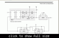
how can i use the pll circuit in figure11 to generate fm signal just to be tested on oscilloscpe.


what i should connect to this circuit and how..
 

how can i use the pll circuit in figure11 to generate fm signal just to be tested on oscilloscpe.
Are you proceeding to PLL chips now?

All you have to connect is a reference frequency at input f1. And set a binary number at the digital inputs Px to define a ratio for the frequency divider.

The shown PLL has no modulation input, so I don't see it directly related to the original question. As KerimF mentioned, an analog modulation input would connected between low-pass and VCO.

The circuit example uses a frequency divdier to make the VCO frequency an integer multiply of the reference frequency. Also most contributions to your post associated a frequency divider with the PLL. But strictly spoken, it's not necessary. The most simply PLL has identical VCO and reference frequency. If still keep your intention to design a PLL without digital chips, i would strongly suggest to omit the frequency divider and go for a 1:1 frequency ratio.

P.S.: It would be helpful, if you tell about the intended carrier frequency and modulation signal.
 
Last edited:
Firstly I assume you have all the components. Do remember the design components in that example is for low frequencies. The output of that circuit will be an FM in assumption that you Input the VCM/VCO voltage according to your input signal(use somewhere between 3.5V-5V). This would be FM but not at typical "FM Radio" Band, but probably much cheaper as well. In case of "FM Radio"band you will need different components.
 
FvM , kalyanasv thanks again for your help

i will build each block shown below


as i said before this experiment just to be tested on oscilloscope, so any simple values for info and carrier signal are accepted..
please can you give me simple circuits for each block..
 

What's your inteded frequency range? Do you have any laboratory function or RF generators available to generate the modulation and carrier signal?
 
What's your inteded frequency range? Do you have any laboratory function or RF generators available to generate the modulation and carrier signal?

yes, there are a function generator available.
information signal for example 2vpp and 5kHz..
 

Use the Function generator to generate the two signals i.e. Carrier and Input. I quite dont get the summer block in it. I would look at this way input: F_input ->phase detector->LPF->VCO-> N.F_input. Then the N.F_input is fed back through a frequency divider of "N" to the phase detector input.
here the phase detector just keeps the input and output in phase.

The above diagram, I am not able to put it to work in my head....The VCO output is an FM. Why is there a carrier input to the phase comparator?
The VCO can also act like FM synthesizer. Any light on that would be useful.

In any case, phase detector you need a diode based Type 1 detector to keep it simple. You could try the VCO components mentioned in my earlier post. Low pass filter a simple RC would do but designed to frequency specs.
 
Then the N.F_input is fed back through a frequency divider of "N" to the phase detector input. here the phase detector just keeps the input and output in phase.
There's no principle difference in loop operation between a PLL using a frequency divider and a 1:1 frequency topology. Omitting the frequency divider has been suggested for a simplified experimental setup without using ICs. You'll find a number of technical PLL applications without frequency divider, by the way.
I quite dont get the summer block in it.
The setup has been explained in post #7 and post#8 by KerimF and biff44. The idea is to set the lowpass cutoff frequency below the modulation frequency. RCinFLA has however mentioned a serious limitation of the low loop bandwidth in post #9.

Another problem is created by not using a frequency divider. The phase shift between VCO output and reference input is limited to maximum +/- 90° (less in practice) with a type 1 phase comparator. So the achievable FM modulation index will be very low. But I fear, there's no alternative "without using any IC or chip".

You have to decide, if the expectable result is sufficient to demonstrate PLL operation. You would be however able to visualize the phase shift between carrier and VCO with a two-channel oscilloscope.
 
You would be however able to visualize the phase shift between carrier and VCO with a two-channel oscilloscope.

I think, this is exactly the reason for why he likes to use PLL to generate an FM signal which is indeed a good idea for an experiment in the least.

I wish I know why he cannot use a simple well known PLL IC, like CD4046.

On the other hand, it may be better to insert the adder before the lowpass filter so that the modulating frequency can be made low though this will produce an 'angle or phase modulation' instead of FM. But actually a PM signal is also FM, the difference is on how we see the original modulating signal carried by it. If it is proportional to the phase variation then it is PM. If the modulating signal is proportional to the derivative of the phase variation only then we can say that the carrier is frequency modulated.

Kerim
 
Status
Not open for further replies.

Similar threads

Part and Inventory Search

Welcome to EDABoard.com

Sponsor

Back
Top