Continue to Site

Welcome to EDAboard.com

Welcome to our site! EDAboard.com is an international Electronics Discussion Forum focused on EDA software, circuits, schematics, books, theory, papers, asic, pld, 8051, DSP, Network, RF, Analog Design, PCB, Service Manuals... and a whole lot more! To participate you need to register. Registration is free. Click here to register now.

[SOLVED] Design of a PIC12F683 based temperature controlled DC fan

Status
Not open for further replies.
Hi omega6,

I have testing your code on EasyPIC7, but this will not work properly...
I placed an oscilloscope on GP0 and GP2 and GP2 sgnal goes from 0 to high (4.84V) with an input voltage (GP0) higher than 1,45V. Room temperature (measured with a digital thermometer IR) of LM35 was 22.5 ° C, which is equivalent to an output voltage of 200mV sensor, with a voltage VDD measured 4,90V.
How is this possible ?
I'm interested in the problems of this assembly, for my own learning.
Many thanks for your answer...
Best regards,
Philippe
 

hi,

I have finish my version, developped on EasyPIC7 and mikroC PRO.
I have used the model of mikroElektronika for a PIC18F45K22.
Code:
/*
 * Project name:
     Design of a PIC12F683 based temperature controlled DC fan
 * Revision History:
      29th September 2015:
       - initial release (omega6)[url] https://www.edaboard.com/threads/343938/[/url]
      09th October 2015:
       - modified release (Philippe LE GUEN) [url]https://pleguen.fr/[/url]
 * Description:
      A simple example of using the ADC library.
      ADC results is used to command a fan motor (DC 12V).
 * Test configuration:
     MCU:             PIC12F683
                      [url]https://ww1.microchip.com/downloads/en/DeviceDoc/41211D_.pdf[/url]
     dev.board:       EasyPIC7
                      [url]https://www.mikroe.com/easypic/[/url]
     Oscillator:      Internal Oscillator (HFINTOSC), 8.0000 MHz (no crystal)
     Ext. Modules:    a DC12V motor fan
     SW:              mikroC PRO for PIC
                      [url]https://www.mikroe.com/mikroc/pic/[/url]
 * NOTES:
     - The motor fan is supply by a +12V auxiliary, commanded by a transistor NPN BC547 with the PWM signal on GP2.
 */


//const unsigned short VREF = 5.0;                         // The current value is +5,0V, so is equal to +5000mV...
const unsigned short VREF = 4.90;                          // Warning ! The VDD power on EaysiPIC7 is 4,90V (measured)
unsigned int adc_sample, Temp_C, Temp_Old, offset;

void main() {

  ADC_Init();                                              // Initialize ADC
  ADCON0 = 0b10000011;                                     // Set VDD as Vref, ANO as analog read, Right justified (very important for a good AD Conversion !)
  ANSEL = 0b00110000;                                      // bit 6-4 ADCS<2:0>: A/D Conversion Clock Select bits (see datasheet)
                                                           //   x11 = FRC (clock derived from a dedicated internal oscillator = 500 kHz max)
  TRISIO.B0 = 1;                                           // Set pin 7 (ANO) as input, used for ADC read
  TRISIO.B2 = 0;                                           // Set pin 5 (CCP1) as output, used for PWM

  PWM1_Init(5000);                                         // Initialize PWM at 19.61kHz (per pic spec-sheet allows 10bit resolution)
  PWM1_Start();

  while(1){
    //Read ADC Channel 1
    adc_sample = ADC_Get_Sample(0);                        // Get 10-bit results of AD conversion
    //adc_sample = ADC_Read(0);
                                  // for indication, VREF is a value in Volt...
    Temp_C = (adc_sample * VREF)/10.240;                   // Calculate temperature in Celsuis
                                                           // The LM35 delivers +246mV at room temperature of +22.7°C case (measured)
                                                           //  which corresponds to +10,83700441mV/°C (10mV/°C in theory), due to component tolerance...
    if(Temp_C != Temp_Old) {

      //if(Temp_C >= 30)
      if(Temp_C > 21) {
         PWM1_Set_Duty(255);                               // Set PWM to 100%
      }
      
      /*if(20 <= Temp_C <= 21) {                           // you can adapted this code for your application testing... (is perfectible)
         PWM1_Set_Duty(127);
      }*/

      else
      if(Temp_C < 20) {
         PWM1_Set_Duty(0);                                 // Turn off PWM
      }

      Temp_Old = Temp_C;

    }

    Delay_ms(500);
  }

}
I also redesigned the complete wiring assembly as on my development board EasyPIC7, in Eagle:
Temperature controlled DC fan 2.png
I also enclose my project writting in mikroC PRO.
Have fun !
Best regards,
Philippe
 

Attachments

  • Temperature controlled DC fan 2_PLG.zip
    73.9 KB · Views: 91
  • Like
Reactions: omega6

    omega6

    Points: 2
    Helpful Answer Positive Rating
Hi PLEG54,

Thank you for taking your time to test the code. I'd like to ask a few questions from you.

GP2 sgnal goes from 0 to high (4.84V) with an input voltage (GP0) higher than 1,45V.
What was the reason for this behavior and how did you solved it ?


Thank You.
 

Hi spirotechgroup,

If you are using mikroC compiler "ADC_Get_Sample" can be used for sampling the ADC values.

- - - Updated - - -

Hi PLEG54,

If you intend on using any PC fans or high RPM fans in the future you should use a BC337. It can go up to 800ma where as the BC547 is rated at 100ma. A better option would be a Logic Level, N-channel MOSFET.
 

Hi omega6,

you are absolutely right, but in my case, the fan is a little bit greedy model, and it was only just to test ...
Indeed, it is more reasonable to uitliser an N-channel MOSFET as it is quicker in switching times, and in fact dispels any quaisment hots.
What interested me was the approach using a PIC12F683 ...

Best regards, Philippe

- - - Updated - - -

Hi PLEG54,

Thank you for taking your time to test the code. I'd like to ask a few questions from you.


What was the reason for this behavior and how did you solved it ?


Thank You.
I do not know why but the maximum voltage delivered by the potentiometer P1 on EasyPIC7 is 4,84V (measured with a digital multimeter FLUKE 77), on the other hand the voltage VCC (and VCC-MCU) is only 4, 90V ...
I think this is due in part to the circuitry of EasyPIC7 map ...

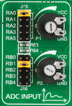
EasyPIC7_ADC inputs.png EasyPIC7_Schema ADC inputs_[640x260px].png

Below the power scheme:

EasyPIC7_Schema Power_[640x286px].png

The DC-DC converter provides only +4,90V regardless of the source, I think it might be possible to go up to +5V by changing the values ​​of the measuring bridge, but the components are SMD ...

Best regards, Philippe
 

Hello...
I'm stupid !

My FLUKE 77 multimeter is not calibrated perfectly, I just checked with my oscilloscope HAMEG HM-407 ...:oops:
It remains for me to send it in for repair ...8-O

The voltage VDD on EasyPIC7 is of +5.0V but against the maximum voltage delivered by the potentiometer P1 (or P2) of the ADC INPUT is +4,93V...
I have slightly modified the program (see previous posts) so that some values ​​of the ADC.
In this picture I posted different values ​​for the ADC:
  • "Temp r" --> the potential difference (mV) between VDD (5.0V) and the voltage supplied to the ADC
  • "MSB et LSB" --> the decimal values ​​corresponding to sampling ADC on 10-bit
  • "Steps ADC" --> the decimal value of the sampling on 10-bit ADC (0..1024)
  • "Value ADC" --> the value of the voltage (in mV) sent to the input of the ADC (PIC18F45K22: AN0)
"Value ADC" + "Temp r" = 5,0V :clap:

Step ADC_[640x360px].png

Thus, I could by placing the probe on my oscilloscope input AN0 check the level of the actual signal at the input of the ADC, and it perfectly matches the reading on the LCD display (4th line )!
So I was able to verify that reading my Fluke is wrong ...
I'm so used to using it that I'm not really realized the error is minimal in this case, because of course it is different from what I measure (the voltage and impedance of the circuit measure, etc ...)

This will serve me a lesson, I méfierai me in the future!
always perform against a measure, this may prove crucial to think ... think about it...

Best regard, Philippe :)
 

My FLUKE 77 multimeter is not calibrated perfectly, I just checked with my oscilloscope HAMEG HM-407 ...:oops:
It remains for me to send it in for repair ...8-O

Just a suggestion on the chance you don't mind opening it up...

If it is like my cheap DMM, then yours may have only one adjustment inside. It makes readings go up or down.

Suppose you hook it up to a fixed voltage regulator? You can calibrate it yourself. Try a few regulators, since the tolerance varies.

Or suppose you try the ohmmeter on 1% tolerance resistors? That is a roundabout way to calibrate the meter within 1% accuracy.

Fluke is a reputable brand and I'm sure they'd do an excellent job of calibrating, but the above is just a possibility in case you like to do it yourself.
 

hi BradtheRad,

you are quite right !
I just used my VCF Controller function generator I stalled at 3000mV.
I built it from a platinum Ready for PIC mikroElektronika it is animated by a PIC18F25K22 to 32MHz, and has a 12-bit DAC on.
I also preset my Fluke 77 it appears to me that full-scale voltage of 4 digits.
That's all I could find as a solution yet, but it is still relatively accurate.
I adjusted the value displayed with the trimmer at the top left of dial gauges.

DAC VCF_[398x640px].pngFluke77 mesure_[360x640px].png

Many thanks for your advise,
Best regards, Philippe
 
Last edited:

Status
Not open for further replies.

Similar threads

Part and Inventory Search

Welcome to EDABoard.com

Sponsor

Back
Top