Continue to Site

Welcome to EDAboard.com

Welcome to our site! EDAboard.com is an international Electronics Discussion Forum focused on EDA software, circuits, schematics, books, theory, papers, asic, pld, 8051, DSP, Network, RF, Analog Design, PCB, Service Manuals... and a whole lot more! To participate you need to register. Registration is free. Click here to register now.

Delay signal by 3/4 clock period?

Status
Not open for further replies.

indu15

Junior Member level 3
Joined
Nov 23, 2005
Messages
31
Helped
0
Reputation
0
Reaction score
0
Trophy points
1,286
Activity points
1,560
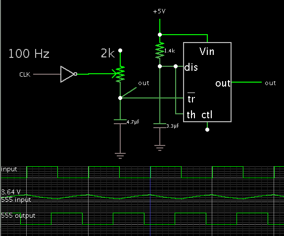
I need to design a circuit to delay a signal by 3/4 clock period. I know by using flip-flops we can design a circuit to delay by 1/2, 1/4, 1/8...clock period but how to delay signal by 3/4 clock period. Can anyone please help me in designing this circuit?

Thanks a lot
 

Possible solution:


The inverter and capacitor convert each pulse to a down-going ramp.
When it gets low enough, it triggers the 555 to produce a 'one shot'.

Adjust the potentiometer so as to yield the desired amount of delay.
 

Thanks BradtheRad for the reply.

What I want to design is a delay circuit that delays the incoming signal by 3/4 and 1/2. For example lets say that the incoming signal is 100 mbps and the delay circuit should delay the signal by 1/2 and 3/4 i.e. 5 ns and 7.5 ns respectively.

Does the solution that you have provided for 3/4 delay works for delaying the signal by 1/2 also by adjusting the potentiometer?

Thanks a lot!
 

I know by using flip-flops we can design a circuit to delay by 1/2, 1/4, 1/8...clock period
If it's true, 3/4 would be easy as well. I presume you don't refer to clock multiplying PLLs?
 

Sorry, what I meant previously by saying that "I know by using flip-flops....." is I know how to do the frequency divider circuit.

Now, the circuit that I want to design is to delay an incoming signal by 3/4 and 1/2.

Thanks a lot!
 

Thanks BradtheRad for the reply.

What I want to design is a delay circuit that delays the incoming signal by 3/4 and 1/2. For example lets say that the incoming signal is 100 mbps and the delay circuit should delay the signal by 1/2 and 3/4 i.e. 5 ns and 7.5 ns respectively.

Does the solution that you have provided for 3/4 delay works for delaying the signal by 1/2 also by adjusting the potentiometer?

Thanks a lot!

If you play with the values then you should be able to get delays anywhere on the pulse period.

However the 555 will not operate as fast as 100 MHz. You'll need to find a different one-shot (monostable multivibrator). It may be necessary to build one from discrete (and fast) devices.

My schematic illustrates the concepts at work (if you wish to experiment):

1) Apply the pulse to a capacitor, to give you a ramp wave. (Invert the pulse first, if need be.)
2) Adjust a comparator to trigger at a certain point on the ramp wave. (The input stage in the 555.)
3) The comparator output goes high for a time that you set, then goes low.

---------------------------------

Another concept is to make a schmitt trigger. You do this by adding a hysteresis loop to the comparator. Then it will trigger at a high point on the triangle wave, and then trigger at a low point. This is a tricky adjustment to get right.

There are schmitt triggers packaged in IC form, which are sufficiently fast for your purposes.
 
  • Like
Reactions: indu15

    indu15

    Points: 2
    Helpful Answer Positive Rating
I think the most reliable way to do this with a sampled or clocked signal is to use a PLL up upshift your clock by 4x, then use the upshifting clock to clock a 3 bit shift register to provide a 3/4 bit delay of the signal. If this is an analog signal, you will need to use an analog shift register; otherwise, a digital shift register will work. The good thing about this approach is that it will adjust to a change in clock frequency as long as it it in the lock range of the PLL.

If you need to delay a continuous signal, it is a lot more complex. Here you would need to calculate the delay needed, then design a filter network to provide this delay. If your clock frequency changes, you would have to redesign.
 
  • Like
Reactions: indu15

    indu15

    Points: 2
    Helpful Answer Positive Rating
Status
Not open for further replies.

Part and Inventory Search

Welcome to EDABoard.com

Sponsor

Back
Top