Continue to Site

Welcome to EDAboard.com

Welcome to our site! EDAboard.com is an international Electronics Discussion Forum focused on EDA software, circuits, schematics, books, theory, papers, asic, pld, 8051, DSP, Network, RF, Analog Design, PCB, Service Manuals... and a whole lot more! To participate you need to register. Registration is free. Click here to register now.

Decoder with input for outputs reset

Status
Not open for further replies.

CuST0M1z3

Newbie level 6
Joined
Oct 25, 2010
Messages
13
Helped
0
Reputation
0
Reaction score
0
Trophy points
1,281
Activity points
1,363
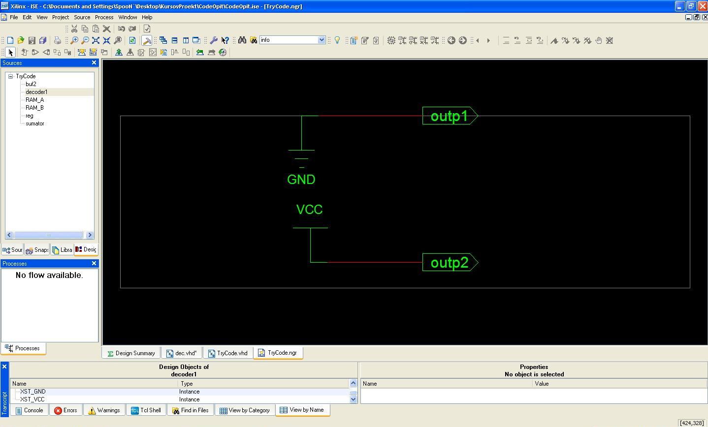
whats wrong?! ERROR - Enumerated value U is missing in case.
entity dec is
port ( din: in std_logic;
reset: in std_logic;
outp1 : out std_logic;
outp2 : out std_logic);
end dec;

architecture Behav2 of dec is

begin
process(reset,din)
begin
if (reset = '1') then
outp1 <= '0';
outp2 <= '1';
else
case din is
when '0' => outp1 <= '0';
when '1' => outp2 <= '1';

end case;
end if;
end process;
end Behav2;
 

std_logic has 9 states ('U', 'X', '0', '1', 'Z', 'W', 'L', 'H', '-'). You need to cover them all in a case statement. The easiest way would be to do this:

Code:
case din is
  when '1'    => outp2 <= '1';
  when others => outp1 <= '0';
end case;

One word of warning though - your logic creates transparent latches. These are not good inside FPGAs.
 

thanks, this is fixed, but now my RTL scheme for decoder looks like this

---------- Post added at 18:28 ---------- Previous post was at 18:28 ----------

51_1288365880.jpg


I am newbie and dont know how to fix this... please help
 

Thats exactly what your code described. It sets outp1 to '0' when reset is asserted, and also to '0' when din = '0'. It never changes to a '1'. The same is true for outp2, it never changes to a '0'.
 

Thats exactly what your code described. It sets outp1 to '0' when reset is asserted, and also to '0' when din = '0'. It never changes to a '1'. The same is true for outp2, it never changes to a '0'.
so i can ignore this warnings: WARNING:Xst:647 - Input <din> is never used.
WARNING:Xst:647 - Input <reset> is never used. ?
I think something in my code is wrong :sad:
 
Last edited:

what are you actaully trying to decode?
I get the feeling your code doesnt meet the spec. Your code is syntactically correct.
 

Hi,

Try below code

Code:
entity dec is
  port 
    ( din   : in std_logic;
      reset : in std_logic;
      outp1 : out std_logic;
      outp2 : out std_logic
    );
end dec;

architecture Behav2 of dec is

  signal decoder_out: std_logic_vector(1 downTO 0);

begin

  outp1 <= decoder_out(0);
  outp2 <= decoder_out(1);

  ------------------------------------------------------------------------------
  -- 1:2 Decoder logic when reset decoder output is at logic 0
  ------------------------------------------------------------------------------
  DECODE : process (reset,din)
  begin
    if (reset) then -- disable output enables
      decoder_out <= "00";
    else
      case (din) is -- dicode logic
        when '0'    => decoder_out <= "01";
        when '1'    => decoder_out <= "10";
        when others => decoder_out <= "00";
      end case;
    end if;
  end process DECODE;

end Behav2;

HTH
 

thank you very much, but now i have any problem with tristate buffers :?
this is my code:
Code:
entity Three_st is
port( T: in std_logic;
I: in std_logic;
O: out std_logic);
end Three_st;

architecture Behav5 of Three_st is

begin
process(I,T)
begin
if (T = '1' and I = '1') then
O <= '1';
elsif (T = '1' and I = '0') then 
O <= '0';
elsif (T = '0') then
O <= 'Z';


end if;
end process;

end Behav5;
WARNING:Xst:736 - Found 1-bit latch for signal <Mtridata_O> created at line 44.
WARNING:Xst:736 - Found 1-bit latch for signal <Mtrien_O> created at line 44.

What`s the problem with this latches, how to ignore them? How they appear?
 

Perhaps any one here can implement the circuit you paste here. But that way you are not going to learn.
Try to resole your self, since self learning is good exercise, forum members are here to resolve problem not to do your work.

Any way this time I wrote code here, even I can write whole code its not more then 10 min job, you will not learn any thing.

From below code try to know why latch is removed and also try to learn how to do sequential design in VHDL and also how to write code for Combination design.
In your case, you are not aware about these two basic thing and you are facing problem. First do enough study then experiment it that is the way you will become an engineer.

any ways you got my idea here is code.

Code:
entity Three_st is
port
  (
    T: in std_logic;
    I: in std_logic;
    O: out std_logic
  );
end Three_st;

architecture Behav5 of Three_st is

begin
  TRI : process(I,T)
  begin
    if ( T = '1') then
      if (I = '1') then
        O <= '1';
      else
        O <= '0';
      end if;
    else
      O <= 'Z';
    end if;
  end process TRI;
end Behav5;

HTH
 

Perhaps any one here can implement the circuit you paste here. But that way you are not going to learn.
Try to resole your self, since self learning is good exercise, forum members are here to resolve problem not to do your work.

Any way this time I wrote code here, even I can write whole code its not more then 10 min job, you will not learn any thing.

From below code try to know why latch is removed and also try to learn how to do sequential design in VHDL and also how to write code for Combination design.
In your case, you are not aware about these two basic thing and you are facing problem. First do enough study then experiment it that is the way you will become an engineer.

any ways you got my idea here is code.


HTH

This is the only thing that i want to do.. i wanna learn VHDL. For now my biggest problems were this two, for which i ask here.I am reading tutorials, but my english is not perfect and i have some problems so i asked here.
I am very grateful for your help and advice,
 

Status
Not open for further replies.

Part and Inventory Search

Welcome to EDABoard.com

Sponsor

Back
Top