Continue to Site

Welcome to EDAboard.com

Welcome to our site! EDAboard.com is an international Electronics Discussion Forum focused on EDA software, circuits, schematics, books, theory, papers, asic, pld, 8051, DSP, Network, RF, Analog Design, PCB, Service Manuals... and a whole lot more! To participate you need to register. Registration is free. Click here to register now.

[SOLVED] Dead Time in SPWM Motor Control Design

Status
Not open for further replies.
Thnkz Sir,

i got it.....

pls check the setup ()

void setup()
{
pinMode(LED_PIN, OUTPUT);
// sets the digital pin as output
Serial.begin(115200); // connect to the serial port
Serial.println("DDS Test");

pinMode(TEST_PIN, OUTPUT); // sets the digital pin as output
pinMode(PWM_OUT_1, OUTPUT); // PWM output / frequency output
pinMode(PWM_OUT_2, OUTPUT); // PWM output / frequency output
pinMode(PWM_OUT_3, OUTPUT); // PWM output / frequency output

// short delay for .5s
digitalWrite(PWM_OUT_1, HIGH);
digitalWrite(lPWM_OUT_2, HIGH);
digitalWrite(PWM_OUT_3, HIGH);

delay(500);//wait for .5 second

digitalWrite(PWM_OUT_1, LOW);
digitalWrite(lPWM_OUT_2, LOW);
digitalWrite(PWM_OUT_3, LOW);


// Setup the timers
setup_timer1();
setup_timer2();

// disable interrupts to avoid timing distortion
cbi (TIMSK0, TOIE0); // disable Timer0 !!! delay() is now not available
sbi (TIMSK2, TOIE2); // enable Timer2 Interrupt
dfreq = 1000.0; // initial output frequency = 1000.0 Hz
tword_m = twoTo32 * dfreq / refclk; // calulate DDS new tuning word
}

In setup () pwm pins 9,10,11 will be high for .5 seconds
after .5s , pwm pins will be low.

some doubts,

if the pwm pins 9,10,11 output will remain high , any problems?? should i set to LOW after .5 seconds??

also delay() function is not used if the timer 0 is disabled.

in program, after the delay () in setup (), timer 0 is disabled .

is this delay(500); will work ??

can u tell me how to get .5s??

Bootstrap Capactior value is 10uf electrolytic //el 200nf ceramic

Vcc is 15.8v

bootsrap diode is Uf4007

thus VOLTAGE across capacitor is 15.8 -1= 14.8V

Is this T = rc = .5 seconds ??

How to get R??

In ckt ,i use no resistance in bootstrap ckt .
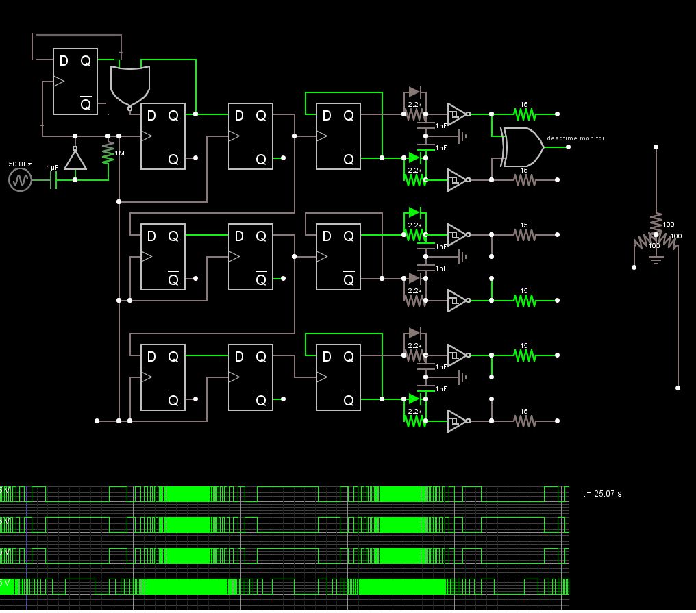
 

Dont need no stinkin Uno

This approach some xtras

1) a sine sweep generator from 1 to 1KHz amplified by inverter for 1 second log triangle sweep for simulation
but could be a Voltage controlled One shot IC like 'HC123
2) a divide by 3 circuit in top left corner
3) 2 stage shift registers under that for phase b & c
4) divide by 2 complementary drivers with asymmetric RC delay into Schmitt triggers for exactly 2us deadtime
5) complementary inverters which could be MOSFETs or bridge driver for big MOSFETs
6) Source current shunts ( in millohms ) for monitoring
7) XOR deadtime glitch sensor to see dead time in gate drivers. could be left out or XNOR or add RC averaging LPF to measure deadtime in mV and adjust with R a pot.

You will need bigger deadtime for fast direction changes and a master Reset for all FF's
The logic may be implemented in a simple CPLD.
6750772500_1426708551.jpg


Ensure the Power on Reset state has all drivers off ( polarity )
 
if the pwm pins 9,10,11 output will remain high , any problems?? should i set to LOW after .5 seconds??

also delay() function is not used if the timer 0 is disabled.

in program, after the delay () in setup (), timer 0 is disabled .

is this delay(500); will work ??

You could let them HIGH, as this is an idle mode operation.

It's OK to use the delay() before deactivating Timer0, as the setup() subroutine is running only at startup.

hus VOLTAGE across capacitor is 15.8 -1= 14.8V

Is this T = rc = .5 seconds ??

How to get R??

In ckt ,i use no resistance in bootstrap ckt .

I was suggesting a random value for that delay (to charge the bootstrap capacitors). It could be much lower indeed. If you want to do some calculations, you should know the capacitor ESR (equivalent series resistance), diode (forward biased) resistance and the power supply internal resistance.

Anyway, an equivalent delay of 5% duty cycle should be enough, because the capacitor should be able to recharge during normal operation even when the PWM signal has the maximum duty cycle (95-98%).
 

Maximum duty cycle of 95-98% means the low-side IGBT is in ON state for at least 2-5% of a complete cycle.
 

Today i checked the dead time ckt ( rcd) with dso,

i got dead time,

but i connected the output of deadtime ckt with optocoupler 6n137.

the output of 6n137 is

no dead time b/w 2 signals(high and low side)

the 2 signal is overlapped with each other ..

now R is 100 OHM and C is 10nf

deadtime is 1.49us

should i increase the dead time ??

also i wana to interface optocoupler ckt with driver ckt,

should i increase deadtime 3 times ??
 

Do you have any capacitor across the 6N137 output and ground? Is the driver connected at the optocoupler output? That's a very strange behaviour.. 1.5us deadtime is much larger than the propagation delay or rise/fall times.

Try to make the measurements with pull-up resitors only (no load). Are you getting the same result with all the optocouplers?
 

No sir, output of 6n137 is directly connected to the LIN/HIN of FAN7392...no capacitor is placed across pin 6 Output and GRND.

yes sir, i jus measure the output of optocoupler nly, driver ic is not connected,

i checked each section by section

pull up resistor is 390 ohm

now i jus float the pin 7 Enable pin.

should i connect THE PIN 7 to VCC ?

Anode Of 6n137 is connected to 5V

cathode is connected to the output of schmitth trigger thru 390 ohm resistor.

output of schmith trigger is 4.8V ( output high)
 
Last edited:

So you don't have any deadtime, even at the optocoupler inputs?

You just said "i got dead time" at the beginning of your post and i thought you actually measured the calculated deadtime (1.5us) at the outputs of the deadtime circuit (inverter gates).

So.. you don't have any deadtime at all?
 

now i jus float the pin 7 Enable pin.

should i connect THE PIN 7 to VCC ?

Pin 7 has an internal pull-up resistor so it might float with no problem.

Do you have any deadtime at the input of optocouplers?


Thnks sir,

Am very happy now,,

now i wana to connect the output of driver to gate of igbt.

i checked the HO frm driver by short with Vs and Com,

pls give some tips for checking , igbt with driver, its my first time
 

Try with a (smaller) resistive load at first. And put a fuse on the DC link to avoid blowing up your IGBTs (crossconduction) during tests.

If everything looks OK (waveforms, timmings, voltages/currents) then you could try with the real load.
 

can i use incandscent lamp 40w,250v,50Hz ??

first

how much voltage is applied to the input ( 3 phase rectifer) ??

i wish to connect single phase 230V,50HZ...to the input.

should i reduce the voltage by using fan regulator ??

bcz autotransformer is available nly on college lab,

itz open only on monday,
i wish to test on tommorow

i have some doubts in driving high side switch .bcz bootsrap drive

design tips for high side switch drive

how much ampere rating of fuse is used ?? 1amp ,250V??
 

Design the fuse depending on your IGBT current ratings (to protect them).

You could use a lower DC link as it has no influence on driver stage.

Yes, an incandescent lamp it's Ok (some use it in line with the DC link too, as a NTC clone).
 

IN DATA SHEETT of fg25n120 IC = 25A

You could use a lower DC link as it has no influence on driver stage.

Did u mean dc link voltage ??

how much voltage is provided for safety operation??

less than 50v. or less than 100v , 100v-300v
 

If you're doing tests using small loads (40W incandescent lamp) and the DC link voltage is 100-300V then just use a 3A fuse, by example (or anything greater, up to 25A).
 

Thnks Red alert,

today i drive real load,3 phase induction motor and vary the freq from 30hz to 50hz , and get speed 900 rpm to 1400 rpm

now i marked this thread as solved,

once again, i thanks to all the EDA members helped me, and this thread wil be helpful to others ,new bie etc

regards

Mobin M K
 

Status
Not open for further replies.

Similar threads

Part and Inventory Search

Welcome to EDABoard.com

Sponsor

Back
Top