mr_mosfet
Newbie level 3
Hello,
Hopefully this is posted in the right area. I'm trying to model the current of the device which is captured by one of the last lines of this code:
(I(p,n) <+ ddt(polar)")
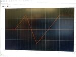
When I implement the code as above I get a flat line for the current (brown curve in the first pic named "ddt_polar"). However I think it should be nonzero in places. I ran the same simulation with the current set to:
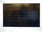
I(p,n) <+ polar;
and got the curve as seen in the second pic named "polar". Clearly the polar variable is changing so ddt(polar) should give me a nonzero current but its not. Why is this so?
Thank you.
Hopefully this is posted in the right area. I'm trying to model the current of the device which is captured by one of the last lines of this code:
(I(p,n) <+ ddt(polar)
Code:
// VerilogA for tech_support3, test, veriloga

`include "constants.vams"
`include "disciplines.vams"

`define M_PI 3.14159

module test(p,n);

	inout p,n;
	electrical p,n;

	real v_prev;
	real v_present;
	real v_c_pos;//positive coercive voltage
	real v_c_neg;//negative coercive voltage
	real v_tp_pos;//positive turning point
	real v_tp_neg;//negative turning point

	real polar;
	real polar_r;
	real polar_tp_pos;
	real polar_tp_neg;
	real polar_temp;

	analog function real f;
		real v; real v_c;//v_c is coercive voltagle
		input v; input v_c;
		f = (2/`M_PI)*atan((v-v_c));
    	endfunction

	analog begin
		@(initial_step) begin
        	v_prev = 0;
        	v_present = 0;
		v_c_pos = 5;
		v_c_neg = -5;
		v_tp_pos = 5;
		v_tp_neg = -5;

		polar = 0;
		polar_r = 1;
		polar_tp_pos = 0;//positive coercive voltage
		polar_tp_neg = 0;//negative coercive voltage absolute value

        	end

		if ((v_present > v_prev) && (v_present > 0)) begin

			polar_temp = polar_tp_neg + 0.5*polar_r*(1 + f(v_present, v_c_pos))*(1 + f(-1*v_tp_neg, -1*v_c_neg));


			if(polar_temp > polar)
				polar = polar_temp;

			if (v_present > v_tp_pos)
				v_tp_pos = v_present;
				polar_tp_pos = polar_tp_neg + 0.5*polar_r*(1 + f(v_present, v_c_pos))*(1 + f(-1*v_tp_neg, -1*v_c_neg));


		end

		if ((v_present < v_prev) && (v_present < 0)) begin

			polar_temp = polar_tp_pos - 0.5*polar_r*(1 + f(v_tp_pos, v_c_pos))*(1 + f(-1*v_present, -1*v_c_neg));

			if(polar_temp < polar)
				polar = polar_temp;

			if (v_present < v_tp_neg)
				v_tp_neg = v_present;
				polar_tp_neg = polar_tp_pos - 0.5*polar_r*(1+ f(v_tp_pos, v_c_pos))*(1 + f(-1*v_present, -1*v_c_neg));


		end

		v_prev = v_present;
		v_present = V(p,n);

		I(p,n) <+ ddt(polar);//current equation currently not working

	end

endmodule
When I implement the code as above I get a flat line for the current (brown curve in the first pic named "ddt_polar"). However I think it should be nonzero in places. I ran the same simulation with the current set to:
I(p,n) <+ polar;
and got the curve as seen in the second pic named "polar". Clearly the polar variable is changing so ddt(polar) should give me a nonzero current but its not. Why is this so?
Thank you.