truly1982
Newbie level 1
how to start pnoise
Hi,
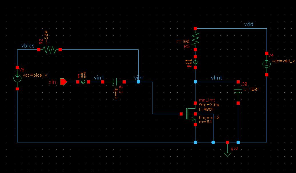
Here is a Pnoise simulation testbench used in DCXO design.
In the schematic, V5 is bias voltage (0.5V), which sets device (mn_lmt) operation point. xin is a sine wave input with amplitude of 1mV, since the amplitude is so small, the operation point of mn_lmt doesn't change. V4 sets the Vds of mn_lmt to make sure mn_lmt works in saturation.
the analysis is:
pss1 pss fund=26M tstab=60n harms=50 maxstep=50p outputtype=all
+ tstabmethod=gear2only maxperiods=99 errpreset=conservative
pmj_lmt (vlmt 0) pnoise start=1 stop=13M dec=5
+noisetype=sources save=all relharmnum=1 maxsideband=2
+saveallsidebands=yes
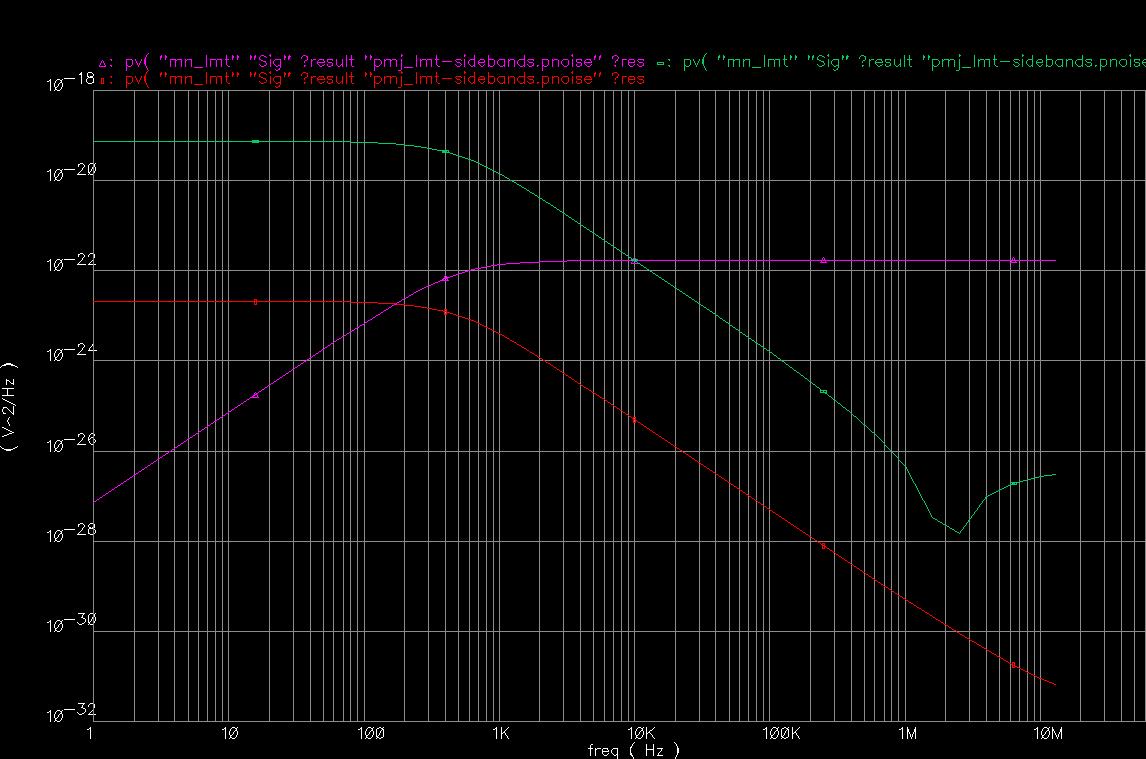
the plot is gate induced noise of mn_lmt in different sidebands.
in sideband "0", the purple curve (high pass) is reasonable, because only see gate induced noise at high frequency.
However, the sideband "1" and "2", which is red and green curve, it becomes low pass, much more gate induced noise accumulated at low freq, which doesn't make sense.


Can anyway explain it?
Appreciate for your help,
Niklas.
Hi,
Here is a Pnoise simulation testbench used in DCXO design.
In the schematic, V5 is bias voltage (0.5V), which sets device (mn_lmt) operation point. xin is a sine wave input with amplitude of 1mV, since the amplitude is so small, the operation point of mn_lmt doesn't change. V4 sets the Vds of mn_lmt to make sure mn_lmt works in saturation.
the analysis is:
pss1 pss fund=26M tstab=60n harms=50 maxstep=50p outputtype=all
+ tstabmethod=gear2only maxperiods=99 errpreset=conservative
pmj_lmt (vlmt 0) pnoise start=1 stop=13M dec=5
+noisetype=sources save=all relharmnum=1 maxsideband=2
+saveallsidebands=yes
the plot is gate induced noise of mn_lmt in different sidebands.
in sideband "0", the purple curve (high pass) is reasonable, because only see gate induced noise at high frequency.
However, the sideband "1" and "2", which is red and green curve, it becomes low pass, much more gate induced noise accumulated at low freq, which doesn't make sense.
Can anyway explain it?
Appreciate for your help,
Niklas.