Continue to Site

Welcome to EDAboard.com

Welcome to our site! EDAboard.com is an international Electronics Discussion Forum focused on EDA software, circuits, schematics, books, theory, papers, asic, pld, 8051, DSP, Network, RF, Analog Design, PCB, Service Manuals... and a whole lot more! To participate you need to register. Registration is free. Click here to register now.

dc mototr driver with direction control from single pin

Status
Not open for further replies.
How do you relate the decay modes with the gate operations? could you give some links or explain?
I want to make this circuit locked anti phase
 
Last edited:

Hi,

I think it is dicussed enough. The thread is going to be endless if we explain every thing again and again.

LOGIC:
You have two inptuts: PWM and DIR
and you have four outputs: LEFT_HIN, LEFT_LIN, RIGHT_HIN, RIGHT_LIN

and there is a relation between inputs and outputs of the logic.

Usually it´s on you to decide if you need fast_decay or slow_decay.
As soon as you decided this you have known requirement for HINs and LINs states.

Klaus
 

Could we add locked anti phase to this circuit?
 

Hi,

With two inputs you can give 4 different input situations: 00, 01, 10, 11
and you get 1, 0, 0, 1 as output.
two times 0, two times 1, but as far as I can see you need a 3:1 output to get the desired slow decay mode function: either 0,0,0,1 or 1,1,1,0
Klaus
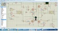
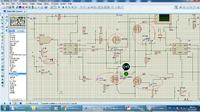
I read in decay modes and I found in simulation using your And gate configuration that
when the direction is zero:
the two low fets are on in the off state time
three fets are on in the on state time

when the direction is one:
two fets are on in the on state time
the same two fets are on in the off state

please look inside circles at the pictures ( mosfet gate voltage )
the off state isn't slow decay mode with both direction but just in one direction which is
the two low fets are on in the off state time


Last edited:

Going back to the start of this thread, I have a question: Could this problem of higher frequency PWM = lower/insufficient Vih to U1 (and gate) be resolved by testing (however, simulation or prototype) for worst case Vih, and using a transistor or logic level MOSFET or two, or totempole, set-up that fits that "worst case" to send the appropriate (5V?) PWM signal into the and gate?

This circuit seems to become more and more complicated with each page, for a "one pin to reverse direction," which perhaps could be achieved with the first circuit posted, or similar variations which would require less components, perhaps. I think, so ask, maybe this circuit could be resolved with 4 NMOS, 2 AND gates, 1 NOT, (1 buffer, maybe), and a suitable rail-to-rail driver for the AND gates for the PWM signal, barely different to the circuit in post #1?
 

Hi,

No, I don't think the problem is the circuit itself.
I rather think the OP doesn't understand the circuit and it's function.

three fets are on in the on state time
It should be very clear that NEVER must be THREE FETs ON at the same time.
Never with a full bridge in any application.

And I'm feeling tired to explain the basics of full bridge motor control again and again.

I hope there is someone out there that can explain it better than me.

Klaus
 
  • Like
Reactions: d123

    d123

    Points: 2
    Helpful Answer Positive Rating
"three fets are on in the on state time"
that's what the simulation shows , i don't imagine it.
I read in decay modes and i understand it better now
thank you for your help
 

Hi,

It's a bit late, but this h-bridge configuration works. H-bridge could be called "X-bridge", as no matter the configuration used or all Ns or Ps or both, etc., that's the way voltage crosses the +V-mosfet-motor-mosfet-0V. Top to bottom = short. Left to right = nothing useful. Top right to bottom left and vice versa = correct path from V+ via motor to ground.

My only doubt is that a low voltage logic gate would not be able to drive a MOSFET for motor control at a higher voltage, and would evidently need a gate driver between the ANDs and the respective NMOS pairs to provide the current necessary and the voltage shift upwards for the specific VGSth required.

motor driver h-bridge.JPG

Glad your circuit is working now.
 

Hi,

Left to right = nothing useful.
I disagree.
Sorry for repeating myself: This is how "slow decay" works. It keeps torque high and speed more constant.
Slow speed is what the OP complains about.

Klaus
 

Hi Klaus,

OKay, fair enough, sorry, I missed the slow decay necessity. I meant that "left to right" in the circuit posted would be pretty useless as stall/brake is implemented with 4 control inputs, not 1 (or 2 depending on how you view that schematic).
 

Status
Not open for further replies.

Part and Inventory Search

Welcome to EDABoard.com

Sponsor

Back
Top