Continue to Site

Welcome to EDAboard.com

Welcome to our site! EDAboard.com is an international Electronics Discussion Forum focused on EDA software, circuits, schematics, books, theory, papers, asic, pld, 8051, DSP, Network, RF, Analog Design, PCB, Service Manuals... and a whole lot more! To participate you need to register. Registration is free. Click here to register now.

DC motor drive which works as normal H-bridge and bipolar drive

Status
Not open for further replies.
Joined
Feb 10, 2021
Messages
2
Helped
0
Reputation
0
Reaction score
0
Trophy points
1
Activity points
30
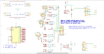
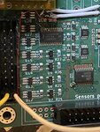
I have run into a peculiar problem. I designed a board to include some 12 V H-bridge circuits for bidirectional control of DC motors and speed with PWM. So far so good. But some of the motors I am to drive have a common terminal. There are many many motors (hundreds perhaps) so rewiring the motors is not an option. For example I might have 4 motors sharing a common wire (5 wires total), and to drive them in arbitrary directions requires the common to be ground and to apply +12 V or -12 V to the other leads to choose direction. I want my circuit to have the capability, logic selectable via MCU GPIO pins, to drive either as a regular H-bridge, or as bipolar, because then for single-polarity situations I will not have to supply -12 V. The board contains a moderately large, 16, number of motor drivers in a tight space and I drive the PWM signal for single-polarity with a LED driver and it works well. I can think of a few ways of adding the bipolar capability, but I am looking for something that is optimal and compact, because of the space constraint. Has anyone done something like this before or have any ideas for a circuit that might work?
 

Hi,

Much text, but not much technical information.
I miss informations about
* exact motor types
* informations about current
* PWM frequency
* H-bridge driving scheme
* space dimensions
* ...

So my simple idea is to use two diodes.
But especially without current and without dimensions I don't know how big the diodes have to be
and whether this is too big for your space.

And without the other infirmations it's hard to say whether diodes can be the solution,
whether it's possible with the motors and how to connect them to the H-bridge.

In the end I have more questions than solutions. Sorry.

Klaus
 

Klaus, a bit more details: the H-bridge is a MP6513. The DC motors each draw less than 150 mA (I don't know the exact type, but they are vacuum-rated with 485 gear ratio so they are quite-nice and run very smoothly). The PWM signal is low frequency, anywhere from 24 Hz to 1500 Hz, and its input controlled by a LED driver (PCA 9685) with 12-bit resolution on the PWM frequency. Two LED driver output pins drive the two H-bridge control pins. The area on my PCB is 3 cm by 1.5 cm which contains (on the top) the LED driver, 7 H-bridges, 4 high-side current measurement devices ZXCT1010 with zener diode + follower to limit voltage input to the MCU ADC port. I have to up the number of DC motors controlled to 12-16 and will be OK with doubling the surface area used. Attached are the schematic and a photo of the section of the board (never mind a couple of bug-fixes ;-)). As it is now it can reverse the 0 and 12 V between the two motor pins, e.g. Va=12 V and Vb=0 V for forward, Va=0 V and Vb=12 V for reverse in the usual way. But the question is how to also add the capability for Va=-12 V and Vb=0 V for reverse without breaking the "normal" way of driving DC motors.
 

Attachments

  • Untitled1.png
    Untitled1.png
    104.1 KB · Views: 89
  • Billede 2-10-21 07.50.32.jpg
    Billede 2-10-21 07.50.32.jpg
    696.4 KB · Views: 89

Status
Not open for further replies.

Part and Inventory Search

Welcome to EDABoard.com

Sponsor

Back
Top