Continue to Site

Welcome to EDAboard.com

Welcome to our site! EDAboard.com is an international Electronics Discussion Forum focused on EDA software, circuits, schematics, books, theory, papers, asic, pld, 8051, DSP, Network, RF, Analog Design, PCB, Service Manuals... and a whole lot more! To participate you need to register. Registration is free. Click here to register now.

Dc-Dc Buck converter

Status
Not open for further replies.

haohaodk46

Member level 4
Joined
Apr 8, 2012
Messages
74
Helped
1
Reputation
2
Reaction score
2
Trophy points
1,288
Activity points
1,789
Hi everybody !
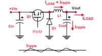
I just made a buck converter circuit that use Mosfet.With Voltage input is 30VDC and i expect output is 12V DC but when i control pwm to G gate of MOSFET but voltage output alway eqal 30V becase have a Capacitor connected output.How i achived 12VDC. Anybody known can help me.Thank !
 

can u please attach the schematic...that would be better for us to understanding your problem...generally a flyback transformer is used to achieve proper voltage and current level.
 

To achieve the "averaging effect" you require, an LC filter must be used at the output. The inductor must be connected between the MOSFET output (source for N-channel and drain for P-channel, assuming the MOSFET is configured as a high-side switch) and the capacitor. A diode must be connected from that MOSFET output and ground, with anode connected to ground. If you have already used the diode and inductor, then probably the inductance is too small.

Take a look here: **broken link removed**

Hope this helps.
Tahmid.
 
This is schematic that i done.Every body can help me.choose incduce and capacitor behave ouput voltage ?
Thanks!
 

Attachments

  • Untitled.jpg
    Untitled.jpg
    108 KB · Views: 162

Your schematic shows no load attached.

Your converter requires a certain amount of load in order to bring your output voltage down to 12V.
 

A big problem I see in your circuit (besides slow gate rise time) is that you're pulling the gate to zero when the NPN transistor is on. When the NPN transistor is off the gate is at +30V. The problem here is that, IRFP9540 is rated for a VGS of -20V, whereas you have -30V which is beyond the rating of the MOSFET. You need to utilize a level-shifting circuit (and a better driver circuit). You might be better off using an N-channel MOSFET with high-side drive, but the choice is up to you.

O, and your circuit has wrong connections - the drain and source connections have been interchanged.

Hope this helps.
Tahmid.
 

I have the same problem .....
1-vgs change with pwm duty cycle and got hot
2- without capacitor output is what i want but i cant make feedbcak because of non-pure DC VOLTAGE
3- with capacitor i have output voltage more than what i calc. and increse up to input voltage
Vin=48 vout=24 current=5A L=80 uH c=470 uF F=200 khz IRF9540n

Without a smoothing capacitor your output will have a large amount of ripple. It is liable to be several volts above and below 24V.

Without a smoothing capacitor your coil will be in continuous conduction mode... 5.8 A from the supply, 5.7 A through the diode. Duty cycle is about 50 percent.

For an 80 uH coil, my simulation works better at a frequency of 100 kHz (rather than 200 kHz). Hysteresis is about 14% above and below 5A.
Smoothing capacitor can be 4.7 uF (rather than 470 uF). It has 700 mA going back and forth through it.

The above figures are theoretical according to simulation.
 
thanks fo reply.........
i am testing for 3 days with these errors
i want to get 24 form 48 volt and 35A
what is the best parameter for that circuit
for high power i will use multiple mosfet in parallel

- - - Updated - - -

and when there is no load ....... input voltage apear at output .... is that normal
 

and when there is no load ....... input voltage apear at output .... is that normal

For a buck converter, this suggests the switch is continually ON. It lets full supply V go to the output.

The capacitor should be rated for full supply V.

thanks fo reply.........
i am testing for 3 days with these errors
i want to get 24 form 48 volt and 35A
what is the best parameter for that circuit
for high power i will use multiple mosfet in parallel

To get 35A in a single buck converter, you would need robust components.

You might consider using interleaved topology. Such as four buck converters, arranged in parallel, but with staggered clock cycles. The burden is shared... thus components need not be so robust.

Screenshot:


The bottom right scope trace shows current coming from the supply. Notice it averages about 20 A (in simulation).

If you prefer to do a triple instead of quadruple, then all components must be rated to carry the greater load.
 

i wont use parallel bauck , i will use multibe MOSET to deistribute current over them
i want this circuit to control 5 motors(2motors-12v-5A max-3 motors -24volt-4Amax)
please tell me best way and parameters , i have acompetetion within 4 days :(
if it possible i need simulation programme that you use
another thing:
whan i use small capacitor >> 10 uf -50 v >> it burn??
 
Last edited:

It's the animated interactive simulator at falstad.com/circuit.

It can export a link. Click on it and it will open the website, load my schematic, and run it on your computer. (Click Allow to load the Java applet.)

https://tinyurl.com/a2ql583

It's a bare-bones illustration of the concept. You can add or remove components to suit your purposes.

To change values, right-click on a component and select Edit.

Your 12V motors should not be connected to 24V power unless you have a proper method to control PWM, etc.

It is no longer clear how much current you need. The figures you gave previously were 5A and 35A. Your list of motors adds up to something different.

whan i use small capacitor >> 10 uf -50 v >> it burn??

When you have a single converter stage powering a heavy load, the capacitor is likely to have 1 or 2 amps going back and forth through it continually. That amount of current travels within a thin foil wrapped inside the capacitor. You can try it, but I recommend you put something protective over it.

If you add a second interleaved parallel converter, it greatly reduces the current in the capacitor.
 

you make phase between switches ??? i want to apply the same signal to multi mosfets and only one coil(or some coiles series or parralel depand on inductor value and current) and capacitor
 

i want to apply the same signal to multi mosfets and only one coil(or some coiles series or parralel depand on inductor value and current) and capacitor

This can be done.
However while you are in this development stage, start with one mosfet. Attach a small load. Find out how much current you can get from the supply. Adjust its operation until you have optimum results. Then add more load. Etc.

The aim is to get the mosfet to turn on fully, and turn off fully. If it is in a middle state during a large portion of the cycle, then it will overheat.

If you add a second mosfet, you will need to balance the loads so each carries the same amount of current.

you make phase between switches ???

Yes, that is how interleaving works. Staggered cycles. One section is charging while the other is discharging (in simple terms).

You don't absolutely have to do it that way, as long as your components can withstand the greater stress when full current goes through them.

On the other hand, supposing your duty cycle is 50 percent, then it is easy to create a second pulse train which is 180 degrees out of phase (inverted). And the stress is divided between two sections.
 
6463132900_1359703867_thumb.jpg


this is my circuit schimatic
i use p-channel MOSFET
another problem is MOSFET Vgs
i use voltage divider to to apply 38 volt on gate and have source 48 so
vgs=-10 and that what i need
when using PWM with duty cycle 50% is measure Vg = 19 v so Vgs= -29 which is harmful forMOSFET where Vgs is +/- 20 volt max
the question is :
i depend on vgs value that i measure on full on or the actual vlaue that i measure with pwm
another question:
voltage divider can drive mosfet
last ques:
i know ( from engineering study :) ) that gate current =0 ( Ig=0)
but i read that the driver must have enough current to be ablr to drive the gate ( gate capacitance charge and discharge)
 

Attachments

  • shamy.PNG
    shamy.PNG
    19 KB · Views: 77
Last edited:

i think your basic problem is mosfet driver circuit.

YOU SHULD USE GATE DRIVER IC FOR EXAMPLE IR2111.
THIS IS VERY SIMPLE GATE DRIVER IC BASICALY DESIGNED FOR MOSFET DRIVING.
 

i will use it but i need answers for my question to correct my informations

and for voltage driver you mention it >>> it's max current is small

another thing --- i have only 48 volt supply >>> do gate driver need specific voltage to operate ?? so in need voltage divider
and with current 1-2 A i will need to use high watt resistors that i don't want to ....
 
Last edited:

15v Vcc is suitable for this ic .
and you can get these voltages by using zener diode .
your load current is dependent on EMOSFET but not on driver ic.
you can use irf450, irf740,irf840 and many more mosfets for heavy currents and also for low current.
also for high voltages like 600Vdc.
 

15v Vcc is suitable for this ic .
and you can get these voltages by using zener diode .
your load current is dependent on EMOSFET but not on driver ic.
you can use irf450, irf740,irf840 and many more mosfets for heavy currents and also for low current.
also for high voltages like 600Vdc.

yea , but i read that driver provide enough current for gate for fast charging and fast full on switching .... zener will provide 12 voltage for driver with 2 A without resistors??
 

so you are worry about gate charge of mosfet.
you can also use a very simple circuit for this problem.
google this " transistor voltage regulator"
you can use d313, d1047 , tip35 2n3055 2n3772,2n3773 for high curren . which are available in your local market.
 

Status
Not open for further replies.

Similar threads

Part and Inventory Search

Welcome to EDABoard.com

Sponsor

Back
Top