Continue to Site

Welcome to EDAboard.com

Welcome to our site! EDAboard.com is an international Electronics Discussion Forum focused on EDA software, circuits, schematics, books, theory, papers, asic, pld, 8051, DSP, Network, RF, Analog Design, PCB, Service Manuals... and a whole lot more! To participate you need to register. Registration is free. Click here to register now.

[SOLVED] Current transformer design and debugging

Status
Not open for further replies.
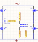
Hi Everyone. I was able to try out all of the suggestion. Put the problem is still persisting. So I wanted to figure out if the current transformer output is a noise or it is really due to current flowing in the H bridge circuit. So I used the following circuit.
circuit_cur_trans_1.png
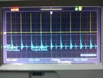
The two ends of the H bridge circuit which is connected to the SMPS isolation transformer was disconnected. Hence there is no path for current to flow through the current transformer and we expect 0V on the secondary of the CT. But this is what I got instead.
IMG_20160619_211340.jpg
Yellow colored waveform corresponds to the MOSFET input waveform.
Blue colored waveform represents the current transformer secondary output.

The circuit used for the current transformer is as follows
current_trans_4.png

I can't understand why I am getting this waveform from the CT when the current through them is zero. Signal amplitude is getting as high as 3V which is triggering my SMPS controller IC off, which could be observed from the yellow colored waveform having a short duty cycle in-spite of it being set at 50%. Can you help me to fix this problem.
 

Hi Warpspeed. I am using this coilcraft CT - CS4200V-01L


Do I still need the cooper sleeve onto my CT.
 

You are snookered my friend, its potted so you cannot add anything.

The more usual type of CT has a round hole through the middle.
Its then just a case of a short sleeve maybe 25mm long slid over the primary wire, then grounding the sleeve.
 
your scope is picking up the (very low power) common mode noise caused by the switching nodes going up (and down) in voltage quickly at the switching edges, try running with actual current in the load and you will then see the two signals...

- - - Updated - - -

also ground one side of your CT o/p to 0vHVDC this will help...

- - - Updated - - -

With your single diode, you only see the current "one way" in the primary, a full bridge of schottky diodes is preferred, and your 10uF cap will take a few switching cycles to charge - why so large? the 100E gives it a 1mS discharge time constant, which might be OK...
 
to be fair, this is an old trick, grounding the sec winding with a low value burden or cap across the winding ends achieves much the same thing...
 

Hi. I used both 10uF and 100nF with no change in effect. Anyways I got the logic and I can use it in my final circuit design. I just replaced bridge with single diode to reduce the no. of diode drops to 1 and see if there is any change in the secondary output.

I tried running with load, it was the same output which I got then. To see if this is a noise, I made the excitation with no path for the current to flow, but still I am getting the same waveform. Are you sure common mode noise amplitude can reach as high as 3V ?
 

Is one end of your CT o/p ckt connected to the oV of the HVDC? this will reduce the common mode noise straight away, esp if you put a good 100nF cap across the o/p of the circuitry also, and your scope probe right on the 100nF cap, without draping the scope wire all over the switching nodes...

A schottky full bridge of diodes is really the way to go on the CT o/p, what is the CT ratio? at 200:1 you need to put 5A thru the primary to get 25mA on the sec, which is 2.5V on the 100 ohms, unless you are dong this you will see nothing but noise....

- - - Updated - - -

a photo of your physical layout would probably explain a lot.... open loops in the switching circuit will get into your scope readings easily....
 
Yes one end of the CT is connected to the 0V of the HVDC when connected with a single diode. How do i connect one end of the CT to 0V of the HVDC if I am using bridge configuration. I will probing across 100nF cap.

You were saying only when 5A(some arbitrary current value) is used as the excitation source, we would have noise in the secondary of the CT. What happens when is no current or it is open circuited ? I want 5A to flow through it but noise is having amplitude as high as 3V which is enough to turn off my SMPS controller.

I will update soon with the physical layout of the circuit.
 

the bridge rectifier goes straight onto the CT o/p wdg, then you take the 0v of that and connect to the 0v HVDC then you put a cap and a burden resistor across the bridge rect o/p, then you measure...
 

I tried that and it is the same. I am not able to get the noise under roof. Still the problem persists.

Regarding the physical layout, were you mentioning the PCB layout ?
 

I think the ringing is coming due to the L1 C3 and I think you can remove the C3 altogether. C1 is way too big and you can use 100 nF there. Is the diode sufficiently fast? If it is a garden type, please replace with a fast diode. That will reduce the junction capacitance. You can also connect the the primary and the secondary sides with a small cap (100 nF will be good enough).
 
Hi c_mitra. I tried removing C3 but it still didn't solve the problem. C1 I was previously having only 100nF but someone in the forum suggested me to have a big cap, so I changed. I will give that a try. I am now using a fast diode. 100nF on the secondary side means, instead of 10uF, use 100nF.
 

At this stage, I would be looking to try a different current transformer.
Preferably one with a hole through the middle that should have far less stray coupling capacitance primary to secondary.
 

If you have bi-polar drive thru the CT, you cannot have single diode rectification of the CT as the reverse volts will break down the 4148 and very possibly kill it, please post your actual circuit on here so people here can make relevant replies...
 

Hi Warpspeed. I will give it a try. The same problem is happening with capped CT and also with first CT which I was using. I guess its not with the CT, something else is there.
Hi Easy peasy. I am now using 1n5819 and I have shifted back to the bridge circuit. Below is my latest circuit.
current_trans_5.png
 

If you just have a wire to one side of the CT going in, with nothing connected to the other side, there cannot possibly be any current in the primary.

The two ends of the H bridge circuit which is connected to the SMPS isolation transformer was disconnected. Hence there is no path for current to flow through the current transformer and we expect 0V on the secondary of the CT. But this is what I got instead.

Yet the spikes you are seeing can only be capacitive coupling between primary and secondary. Only way to fix that is with another different current transformer.
 

you need to connect up the WHOLE circuit with just a modest load in order to see realistic things, operating with the bridge disconnected just gives odd results....
 

Status
Not open for further replies.

Similar threads

Part and Inventory Search

Welcome to EDABoard.com

Sponsor

Back
Top