Welcome to our site! EDAboard.com is an international Electronics Discussion Forum focused on EDA software, circuits, schematics, books, theory, papers, asic, pld, 8051, DSP, Network, RF, Analog Design, PCB, Service Manuals... and a whole lot more! To participate you need to register. Registration is free. Click here to register now.
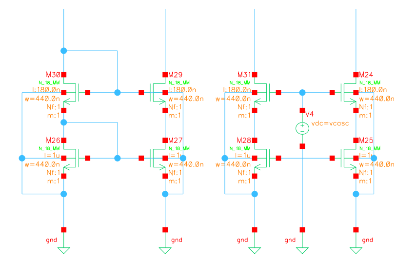
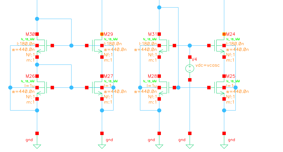
The left circuit is not the Widlar current mirror, it is a simple cascoded current mirror. The widlar employs emitter degeneration only at the output side and it has negative feedback to increase the output resistance.
The difference between the circuits is the requirement is biasing requirements and voltage headrooms.
Left circuit - vin(min) = 2(vth+vod)
Right circuit - vin(min) = vth + vod, need extra branch to generate vcasc.
What's the difference to the simple current mirror? Respectively why is the performance of the circuit that includes the cascode into the diode connected mos so much better incomparision to the normal current mirror?
The transistors at the bottom defines mostly the accuracy of the current mirror. A current mirror is more accurate when the bottom transistors see the same vds. In the left circuit, when you sweep vcasc, both bottom transistors are seeing the same vds because the top transistors have the same vgs. On the right mirror, the diode connected transistor has a fixed vds = vgs. When you sweep vcasc, M36 has a changing vds and that is why the current keep changing more on the right current mirror. Note that from above 1 V of vcasc, the top right transistors seem to go into triode. You should consider generating vcasc using diode connected transistors to improve performance and make it practical.
This site uses cookies to help personalise content, tailor your experience and to keep you logged in if you register.
By continuing to use this site, you are consenting to our use of cookies.