Continue to Site

Welcome to EDAboard.com

Welcome to our site! EDAboard.com is an international Electronics Discussion Forum focused on EDA software, circuits, schematics, books, theory, papers, asic, pld, 8051, DSP, Network, RF, Analog Design, PCB, Service Manuals... and a whole lot more! To participate you need to register. Registration is free. Click here to register now.

Control circuit for swtiched capacitor resonant converter ??

Status
Not open for further replies.

vamsi57

Newbie level 4
Joined
Jan 8, 2012
Messages
6
Helped
0
Reputation
0
Reaction score
0
Trophy points
1,281
Activity points
1,325
I want to design a control circuit for switched capacitor resonant converter with phase shift control having four mosfet switches.The gating pulses to the mosfets are given with a phase shift...as shown...
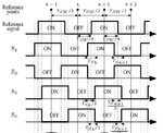
phase shift.jpg

switching frequency is 20KHz and the.....and the phase shift for first 2 switched lags...phase lead for the next 2 switches...

so,i need help in designing the control circuit to produce pulses as shown above......
 

That’s similar to a multi-phase clock signal generating circuit.
Need more data in order to consider a solution for the circuit. Missing important relation between TSW and TSk.


Maybe you can adapt the LTC6909 circuit:
http://cds.linear.com/docs/Datasheet/6909fa.pdf
 
Tsw is the total time period and Tsk is the time by which the phase shift is done...

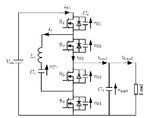
I am attaching the main circuit for which i need the control circuit.

scrc.jpg

S1 and S2 lead from the reference signal by Tsk/2 and S3,S4 lag from the reference signal by Tsk/2.
 

A possible solution to use a shift register for flexible multiphase clock generation.
Use the driving signal of the first phase as the input of a shift-register .
In this way a delay is obtained equal to the length of the shift-register multiplied by the clock cycle. The total length of the shift-register is at most equal to resolution of the duty cycle, while each driving signal is extracted from the position obtained
Cx= (x-1) R/N
where:
x = the phase number from 1 to N,
N = the number of phases
R = the resolution of the duty cycle, which is equal to the range of the counter.
These delays are equivalent to the desired phase-shifting operation, see the diagram attached:
 

Attachments

  • SR multiphase.JPG
    SR multiphase.JPG
    68.4 KB · Views: 76
  • Shift register.JPG
    Shift register.JPG
    45.5 KB · Views: 81

A possible solution to use a shift register for flexible multiphase clock generation.
Use the driving signal of the first phase as the input of a shift-register .
In this way a delay is obtained equal to the length of the shift-register multiplied by the clock cycle. The total length of the shift-register is at most equal to resolution of the duty cycle, while each driving signal is extracted from the position obtained
Cx= (x-1) R/N
where:
x = the phase number from 1 to N,
N = the number of phases
R = the resolution of the duty cycle, which is equal to the range of the counter.
These delays are equivalent to the desired phase-shifting operation, see the diagram attached:


thankyou very much,i will try it.
 

Status
Not open for further replies.

Part and Inventory Search

Welcome to EDABoard.com

Sponsor

Back
Top