riksworld
Newbie level 6
Hi all,
I am currently putting together a system for my new aquarium setup which is arriving in 4 weeks time, currently I am thinking of purchasing the following items:
1 x ETH-RLY16 (https://www.robot-electronics.co.uk/htm/eth_rly16tech.htm)
1 x 1400 L/H AQUARIUM PUMP (**broken link removed**)
I know the ETH-RLY16 can support 240V at 16Amps which is more than enough for the pump, which is around 0.10 Amps, it supports Common, Normally open & Normally closed, the controller is powered by a 12V psu.
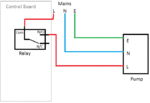
Its been a long time since I have done anything like this before with relays and i cant remember how you wire up a pump to this type of setup, could anyone on here please kindly post some help.
Any reply`s would be thanked.
