Continue to Site

Welcome to EDAboard.com

Welcome to our site! EDAboard.com is an international Electronics Discussion Forum focused on EDA software, circuits, schematics, books, theory, papers, asic, pld, 8051, DSP, Network, RF, Analog Design, PCB, Service Manuals... and a whole lot more! To participate you need to register. Registration is free. Click here to register now.

[SOLVED] Constant Current power Supply

Status
Not open for further replies.
Hey,

I am little worried about thermocouple effect.
How would I calculate the thermocouple effect in conductors / DUT
Any formulas available.
Now looking onto the following cons and pros for each systems

Looking into the DC exited system we will require a zero drift opamp with high gain ➕ single ended 18 bit/16 bit ADC ➕ a display unit

And now looking onto AC exited we have zero drift opamp ➕ Bipolar adc ➕ display unit.

That's pretty straight forward.
But both of the excitation techniques have their pros and cons.
Like Ac ➡ inductive effect and skin effect
And DC ➡ thermocouple effect
 

Hi,

Like Ac ➡ inductive effect and skin effect

but you have a ucontroller and software...

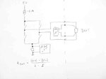
Four your application it is ok to switch polarity every 100ms,
and then you could wait 90ms to take the measurement.

With that low ohmic loads i think 100us would be sufficient.
And for filtering out noise i´d take a lot of measurements every polarity and calculate the average.

With AC excitation you do not need to calculate the thermocouple voltage.
And if you do the measurement and the calculations right: not only DC is canceled out but also other unwanted frequencies like mains...


Klaus
 

Hi,
Could u please show a detailed block diagram of your method please!
 

Hi,

DSC06655.JPG

Measuring of "I" is not AC because the thermocouple effects here are low.

Klaus
 

And how much drift a constant dc supply would cause in readings?
 

Hi,

Drift in currentsource are canceled out.
The higher the current, the higher the voltage across DUT.

The influence of thermocouple voltage mainly depends on pcb layout.The main target is to keep joints with same material combination on same temperature.

Klaus
 

So if we use copper clips for our testing of DUT made of Al Or CU than at how much factor should the drifting of values take place (error %)

- - - Updated - - -

And being to sense the voltage drop across DUT a zero drift opamp like ltc 2050
From linear would do that job with a feedback gain of 10,000.
 

Hi,

With AC excitation the thermocouple effects are canceled out.

For to calculation on DC signal one needs to know all joint material combinations an the temperature of every single joint.
But since it is canceled out it makes no sense .....

Klaus


Added:
Even the opamp offset voltage of the DUT sense amplifier is canceled out.
Low drift is important. But i like the idia to use a very low offset opamp.
If there is no error, there is no need to comensate it.

Klaus
 

Hi,
Finally I am now starting to design the first schematic of this circuit using a 5 Amp Transformer rather than a H bridge inverter and a zero drift opamp with a gain of 10,000 plus a bipolar adc and display unit.

I hope to get these work done in the right direction.

- - - Updated - - -

50 hz mains frequency might not produce any inductive effect based drifts...Right!
 

Tracing shorts is pretty easy if you know what kind of short you are looking for.

For Plated thru hole shorts on an inner layer gap, it may blow like a fuse with 5A. If not , just dump a big charged (1000uF 5V) cap after you locate the closest vias, to blow the short and avoid overheating the good traces.

To locate a short with 5A from 1u to 1m Ohm only needs 5uV to 5mV drop plus external interface "kelvin bridge" losses.

A single LiPo cell will easily provide this with some wire inbetween to limit the current or with low duty cycle to avoid cell damage. So if you don't happen to have a 5uV DMM then a classic 3 stage Instrument Amp with null adjustment and a gain of 1000 to feed any 1mV resolution DMM should work. The null adjust could also null circuit losses.

15198-figure_1[1].jpg

Gold contacts might be best for anti-corrosion but not flash plated ones, get heavy duty spring loaded Pogo Pins.

Using a 3 or 4 probe method you can locate a short pretty fast. 2 to supply power from a current limited battery thru an ammeter to the furthest vias and the 3rd probe pair to measure the drops. Since the short is low impedance , it is pretty immune to noise. But be sure to add bidirectional OVP or back-back diodes to clamp any inductive loads when released.

Also I think 100mA is plenty to locate a 1uOhm short.
 

Attachments

  • 15198-figure_1[1].jpg
    15198-figure_1[1].jpg
    52 KB · Views: 79

Hi Ashkar.

I don't know about your transformer, it's connections and so on.
So you have to be sure how to make it working...

In my draft you see just four swiches. With lower current i'd use cmos analog switches. But with 5A i'd use mosfets. The switched signal comes from the DC 5A constant current source. So in one time the 5A goes forward to the DUT and in the other time the 5A go reversed through the DUT. That's all - for hardware. The ucontroller controls the switching as well as the ad sampling.
To cancel out mains influence one has to control the switches exactely with 1/x of mains frequency.
If you do it with my given 100ms you cancle out 50Hz as well as 60Hz.

With an opamp gain of 10000 you need an opamp with unity gain of 10000 x 10 Hz x 1000 (resolution) to be on the safe side.
This is 160dB.
I'd go for two stages with gain of 100 each.

Inductive effects:
If you want to test a piece of wire then i'd expect low inductivity. If you want to test the DC resistance of a power plant mains tranformer it surely does.
If you go for your 50Hz transformer solution you are fixed to this frequency. If you go for the swiches, then the software can select the desired freqency.

Klaus
 
  • Like
Reactions: Ashkar

    Ashkar

    Points: 2
    Helpful Answer Positive Rating
Hello Klaus,
I figured out that an opamp with zero drift
•Low offset: 10 µV max
•Low drift: 0.05 µV/°C max
•Low noise (1/f corner at 0.08 Hz)
◦6 nV/√Hz @ 0.5 Hz
◦0.1 Hz to 10 Hz = 125 nVP-P

•Open-loop voltage gain
◦300 dB (typical)
◦200 dB (minimum)

•Rail-to-Rail™ output swing
•Slew rate: 5 V/µS
•Power rating: 3.6 mA

So now we need to set up 2 opamps with 100 gain each.

- - - Updated - - -

Its an opamp from cirus logics.
 

Hi,

Opamp values sound good.
With 300dB you need only one opamp.

I never heared about opamps with 200dB open loop gain.
It is a gain of 10000000000.Are you sure this is true?
300dB means gain of 1000000000000000 (are this 15 zeroes?)

Klaus
 

Hi Klaus,
I am sure that the open loop gains are 200 -300 db .
So that means we would require just a single opamp to do the signal gain.but do we need a buffer in between with a unity gain.
 

Hi,

With the given values there is no need for an extra buffer.

Klaus
 

Hello Klaus,
kindly look at the schematic below for the input side gain amplifier that is used with Analog Devices OP37.

- - - Updated - - -

Page no 11
Fig 4a
On OP37 data sheet
Actually I am unable to upload a diagram for that
 

Hi,

The circuit 4a is an "instrumentation amplifer".
Thanks for guiding me to this curcuit.

???

Klaus
 

Hey Klaus,
So I need to ask that is this the right configuration to use the opamps in that configuration so as to get our required gain or just a simple 1stage gain configuration is fine to be used!
 

Hi,

Both input signals are very near to zero voltage. Also both signals are very low ohmic.
So a simple differential opamp circuit is ok.
mind to use
* either opamp with common mode input range including gnd
* or opamp with negative supply.

Btw. What's the name of the cirrus opamp?

Klaus
 

Hello Klaus,
could you please upload a schematic of a differential amplifier.
And the opamp is cs3002.
 

Status
Not open for further replies.

Similar threads

Part and Inventory Search

Welcome to EDABoard.com

Sponsor

Back
Top