Zaphappy
Junior Member level 2
- Joined
- Feb 28, 2011
- Messages
- 21
- Helped
- 1
- Reputation
- 2
- Reaction score
- 1
- Trophy points
- 1,283
- Location
- Campbell, CA
- Activity points
- 1,476
I have an instrument with (3) 2 terminal inputs. Each labeled U- U+ (3 channels)
All inputs measure 4 megohms and any terminal measures 4 megohms between.
With meter across chan 1 (U- U+) and I short chan 1 U- to chan 2 U- resistance drops to 3 megohms.
When I additionally short all U- inputs together I get 2.67 megohms.
If I measure across any channel and short across another the resistance remains 4 meg.
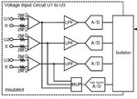
How the heck to I figure out the actual circuit ?
This is a 3 phase power analyzer with "isolated" inputs. I need the equivalent schematic so I can adapt input dividers.
I have attached the manufacturer schematic. Still confused

Attachments
Last edited: