Continue to Site

Welcome to EDAboard.com

Welcome to our site! EDAboard.com is an international Electronics Discussion Forum focused on EDA software, circuits, schematics, books, theory, papers, asic, pld, 8051, DSP, Network, RF, Analog Design, PCB, Service Manuals... and a whole lot more! To participate you need to register. Registration is free. Click here to register now.

Confused by 555 pinout...

Status
Not open for further replies.

itsallgood

Member level 2
Joined
Mar 15, 2002
Messages
48
Helped
0
Reputation
0
Reaction score
0
Trophy points
1,286
Activity points
329
Hi all,

I'm confused by 555 timers when looking at circuit diagrams.

If the 555 is a rectangle with 4 pins on one side, and 4 on the other. And they are numbered 1 to 8 anti-clockwise from the notch.

How do you use circuit projects where the chip is shown square, and the legs are in no order?
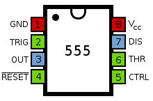
A 555 timer:
220px-555_Pinout.svg.png


A circuit:

**broken link removed**

The chip has pins all the way round, and the order is wrong???

I'm looking at this page here:

**broken link removed**

Any help would be great.

Cheers.
 

A schematic diagram can have any pin arrangement that is physically possible ..
I don’t think when your friends arrive to your place they all park their cars in the same sequence at all times ..

Rgds,
IanP
 

The schematic has nothing to do with the physical description of the chip. You have to be a little careful, as semiconductor chips are often available in several very different package styles. You have to make sure you are connecting the right pin to the right function on your project.

In the case of the LM555, you are in luck, though. They all use a 8 pin rectangular package, where pin 1 is ALWAYS the one next to the small dot, or if there is not small dot, the pin to the left of the little horseshoe indentation when viewing the chip from the top.
 

Drawing a chip with the pins in a non-sequential order is done simply to make the circuit diagram easier to follow.

Keith
 

Just make sure the pin number is correct accordingly to the circuit example.
Don't worry about where the leg are. They are just picture.
MODERATOR - SIGNATURE LINKS ARE NOT ALLOWED
 

    itsallgood

    Points: 2
    Helpful Answer Positive Rating
Status
Not open for further replies.

Part and Inventory Search

Welcome to EDABoard.com

Sponsor

Back
Top