leebluer
Member level 4
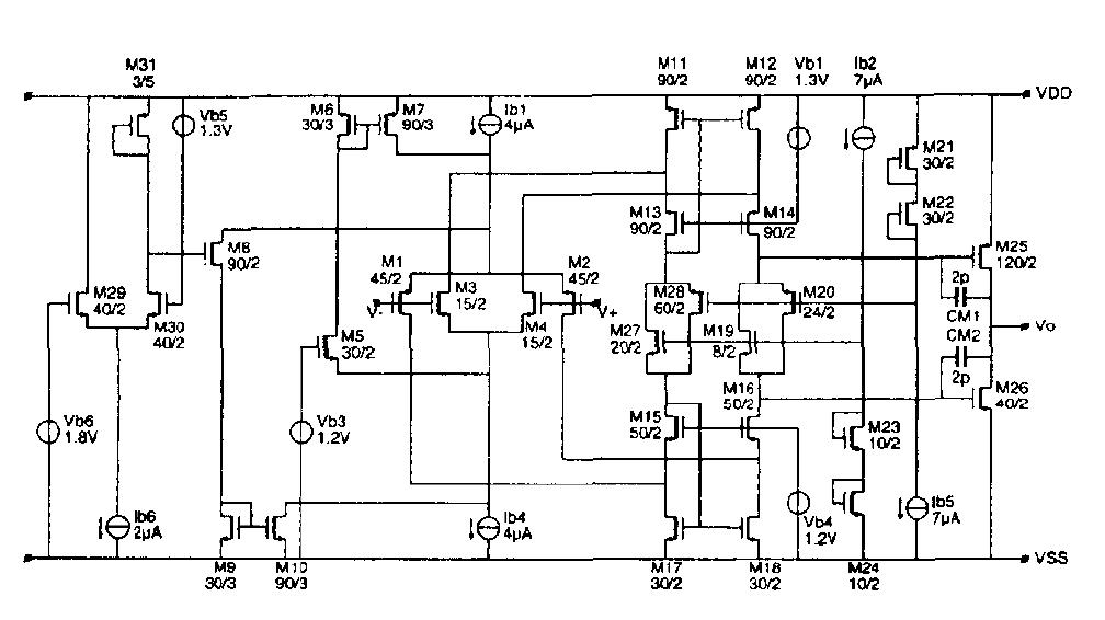
Class AB OPA is designed to drive 0.1uF CL, which use floating bias structure shown in the below. Up to now, I couldn't compensate OPA with good stability.
With 0.1uF CL, simple miller CAP is hard to seperate the two poles, and cause worse stability.
Details are below
1. With Miller Compensation, output pole is push to Po~Gmo/[CL*(1+C1/Cc)]. By 0.1uF CL, Po is around 20KHz (calculate & simulation)
2. As for 120dB DC gain, ~nF Cc should be used to push Po out of Unit Gain Band. ~nF integrated MOS CAP is unsuitable
3 Refer to Allen's book (buffered OP chapter), shunt negative feedback is used, while it complicates design (add A1+A2 & some current balance loop)
In general, how to deal with big CL, e.g. ~0.1uF? Many paper are dealing with several pF CL.
Thanks in advance