Continue to Site

Welcome to EDAboard.com

Welcome to our site! EDAboard.com is an international Electronics Discussion Forum focused on EDA software, circuits, schematics, books, theory, papers, asic, pld, 8051, DSP, Network, RF, Analog Design, PCB, Service Manuals... and a whole lot more! To participate you need to register. Registration is free. Click here to register now.

Common Centroid Layout of DAC

Status
Not open for further replies.

Monady

Advanced Member level 4
Joined
Dec 1, 2008
Messages
109
Helped
12
Reputation
24
Reaction score
3
Trophy points
1,298
Activity points
2,151
Hello,

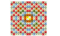
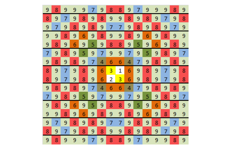
I am looking for a common centroid layout for a binary weighted DAC and in a thesis online found an arrangement, but I have had a hard time figuring out a pattern in this placement. The figure below is the capacitor array placement and each number in this figure (i= 1, ...9) shows to which capacitor (Ci) each unit cap belongs. I appreciate if someone helps me finding a pattern for this placement, since I want to use this pattern to draw layout for another DAC with different resolution.


Thanks
 

In capacitor array a very important is to compensate a parasitic capacitances of connections so sometimes common centroid could produce more drawbacks than "more simple" pattern. In the last (or one before) issue of IEEE Trans. on Comp. Aided Design I found a paper optimising the array of binary cap-dac (unfortunately I don't remember the name of this paper and an author's names also...)

Backing to the showed layout. It's in fact not a clear common centroid, i.e. at the right-top corner the 9bit is not "mingled" enough. The classic common centroid layout You can find in classic paper about current steering DAC from IEEE SSC of **broken link removed**
 
  • Like
Reactions: Monady

    Monady

    Points: 2
    Helpful Answer Positive Rating
Synopsis use something like this

The pattern has the centroid inverse weight (1,2) with guarding (3) and sidebands 4~9

The weighted average improves accuracy from 10 to 12 bits and reduced size improves speed into microwave DAC speeds.

It is like decimating a 1 D filter into 2D space.
5.9.jpg
 

In capacitor array a very important is to compensate a parasitic capacitances of connections so sometimes common centroid could produce more drawbacks than "more simple" pattern. In the last (or one before) issue of IEEE Trans. on Comp. Aided Design I found a paper optimising the array of binary cap-dac (unfortunately I don't remember the name of this paper and an author's names also...)

Backing to the showed layout. It's in fact not a clear common centroid, i.e. at the right-top corner the 9bit is not "mingled" enough. The classic common centroid layout You can find in classic paper about current steering DAC from IEEE SSC of **broken link removed**

Tnx Dominik! I agree about the problems that parasitic caps may generate. I will most likely use the approach in the paper you said.

Synopsis use something like this

The pattern has the centroid inverse weight (1,2) with guarding (3) and sidebands 4~9

The weighted average improves accuracy from 10 to 12 bits and reduced size improves speed into microwave DAC speeds.

It is like decimating a 1 D filter into 2D space.
5.9.jpg

Thanks for your comment! Frankly I could not quite understand what you said. I have not worked with Synopsis products for a while, but as far as I remember they did not have layout drawing software, right?
I also did not get what you meant by guarding, sidebands and also the figure you attached, would you please give me a reference about it?
 

Status
Not open for further replies.

Similar threads

Part and Inventory Search

Welcome to EDABoard.com

Sponsor

Back
Top