Vermes
Advanced Member level 4
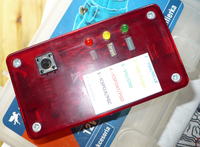
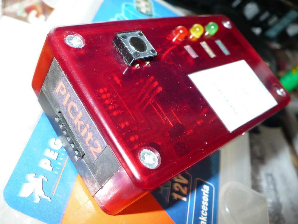
This is a clone of PICkit2 programmer which can be home made in every electronic workshop. Before you create such a clone, it is good to get familiar with specification and features of this programmer.
The program is based on: **broken link removed**, Projekty PIC
Function of a three channel logic analyzer with sampling from 1 MHz is very important feature of this project, as it proves watching PWM waveforms and can be used instead of oscilloscope (under certain circumstances).
More pictures: LINK
PCB was modified – all resistors were changed into slightly bigger ones, and it was adjusted to Z-76 housing. The microcontroller was programmed using .HEX file found **broken link removed**.
The circuit was mounted classically in a way so that it fits the housing. Transistor should be tilted or put on the microcontroller. If you find it difficult to find IRF9Z34, you can use IRF9540 instead.
When the circuit is assembled and programmed, your computer should detect a new HID interface device. The software can be downloaded from **broken link removed**.
Next, run the program and check whether the programmer communicates with it. When it is okay and green diode lights up, indicating the circuit supply, check the VDD PICkit2 off and then the yellow diode should light up, indicating switching on the supply voltage which can be used to power the microcontroller software. In order to check the red diode and the button, select Tools->Logic Tool... in the menu and set correctly, then press RUN. The red diode should light up then.
You can also check the circuit by starting it from the main window Tools->Troubleshoot and follow the instructions. In the first step, the supply voltage is examined, despite the changes in the voltage, it will always be 5V in the circuit. In order to program microcontrollers powered by another voltage, you should lead the supply voltage from the outside of the proper value.
Click Next two times and check the voltage from the microprocessor in the circuit – voltage on pin MCLR – it should be about 12V and it is necessary when microcontrollers programming, because it initializes the state of programming.
Except the three channel logic state analyzer, the device provides direct converter USB → UART. Home made programmer is much cheaper than the original one from Microchip.
Pictures:

Link to original thread (useful attachment) - Mój klon PICkit2 - programator Microchip