bigdog
Junior Member level 2
clock multiplexer
Hello,
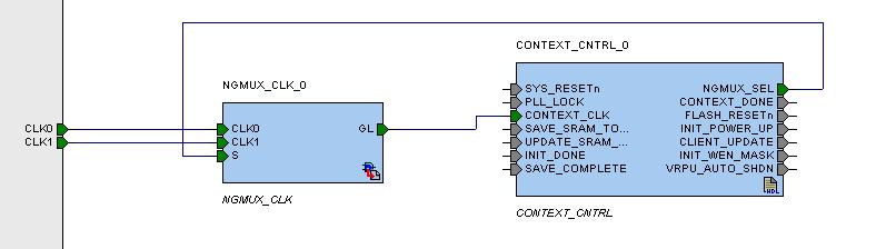
I have two input clocks, CLKA and CLKB.
They go to a multiplexer directly from input port then generate a new clock CLK_SYS as the system clock of the whole circuit, but the select signal of the clock multiplexer comes from the CLK_SYS domain and its value is not a constant.
So, how should I define the clocks of this circuit?
Note: I use Synopsys design complier.
Thanks!
Hello,
I have two input clocks, CLKA and CLKB.
They go to a multiplexer directly from input port then generate a new clock CLK_SYS as the system clock of the whole circuit, but the select signal of the clock multiplexer comes from the CLK_SYS domain and its value is not a constant.
So, how should I define the clocks of this circuit?
Note: I use Synopsys design complier.
Thanks!