Continue to Site

Welcome to EDAboard.com

Welcome to our site! EDAboard.com is an international Electronics Discussion Forum focused on EDA software, circuits, schematics, books, theory, papers, asic, pld, 8051, DSP, Network, RF, Analog Design, PCB, Service Manuals... and a whole lot more! To participate you need to register. Registration is free. Click here to register now.

Class AB output stage can theoretically drive infinite current into load

Status
Not open for further replies.

sthota04

Newbie level 5
Joined
Oct 26, 2015
Messages
9
Helped
0
Reputation
0
Reaction score
0
Trophy points
1
Activity points
67
Can someone explain how class AB can theoretically drive infinte current into output load. How is it different from class A stage?
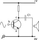
 

A class-AB output stage has a maximum allowed output current rating and a class-A circuit also has a maximum allowed output current rating. If this current rating is exceeded then the output transistors will get too hot and/or burn out and the driver transistor also will get too hot and/or burn out. The amplifier has negative feedback so if the output is shorted then the circuit tries as hard as it can do deliver enough current to destroy itself unless there is a short circuit protection circuit to limit or disconnect it.
 

Can someone explain how class AB can theoretically drive infinte current into output load. How is it different from class A stage?

The comparison that comes to mind is an audio amplifier.

a) Class A operates on a single-ended power supply, a convenience. To permit this the speaker needs a capacitor in series, passing audio in a give-and-take action but blocking DC. Too small a Farad value reduces overall volume and especially bass response.

You can make the capacitor a very large value, yet there is a limit to the amount of current it can carry, without distorting the waveform.

* There is a simple class A which has a collector resistor in the current path during 1/2 of the cycle. You can improve it by making a half-bridge instead. It is still class A (according to the judgment of one expert), however then you need to be concerned with proper biasing and null distortion. And you still have the capacitor inline with the speaker.

Class AB needs no capacitor. You can drive the load at full supply voltage during each half of a cycle.
 

In theory there is no difference between theory and
practice.

Especially if it's a pretty lame theory. Like one where
every component is ideal.
 

Hi,

There are a couple of different Class A schematics.
The following picture shows one circuit where the "limited current" is a bit obvious.
ClassA.png

1) if the bjt switches to GND, then only a small pulse of high current can be driven through the load.
2) if the bjt releases, then the current is limited by the R. The same current also (re-) charges the capacitor

3) sine signal (or any other signal that is amplified with not too much distortion)
In case the bjt pulls low then the capacitor needs to be charged before to drive a current into the load .. the charging of the capacitor takes place in the positive halfwave, when the bjt releases (partly).
Charging and discharging need to be equal. If charging current is limited by R, then this means discharge current is also limited by R.

Klaus
 

Status
Not open for further replies.

Part and Inventory Search

Welcome to EDABoard.com

Sponsor

Back
Top