Continue to Site

Welcome to EDAboard.com

Welcome to our site! EDAboard.com is an international Electronics Discussion Forum focused on EDA software, circuits, schematics, books, theory, papers, asic, pld, 8051, DSP, Network, RF, Analog Design, PCB, Service Manuals... and a whole lot more! To participate you need to register. Registration is free. Click here to register now.

circuitry problem for 16f877a

Status
Not open for further replies.

emperror123

Member level 5
Joined
Dec 11, 2010
Messages
86
Helped
1
Reputation
2
Reaction score
1
Trophy points
1,288
Activity points
1,880
dear all

i have trying to do my circuit cracked my head for whole night, but unable to solve

my project is using PIC16f877a, my coding might be very long, around 500 lines
since i have connected to my circuit with power supply, but unfortunate it can't be work

all have voltage which is around 5v when i measured from battery to whole circuit, but when i measured from PIC there is no voltage flow.

how can i be solve this problem?
 

has voltage across the battery 5volt ? its voltage is low it there has a short circuit or a component may shorten .
 

from adpter convert the voltage to 5v,
after that all components has voltage, i tested 1 by 1 by buzzer, there is a connection but there neither short nor open
 

upload your circuits .it may easy to find the error if any
 

problem might be due to the wrong configuration of directional resistors(TRIS) ..... please check it properly. if this doesnt solve your problem then check wether your IC is in working state or not.
 

Have you checked the ground connection(s)?

Also, the 16F877A has 2 sets of Vdd, Vss. They both need to be tied together.

Regards,

Anand Dhuru
 

Does the 7805 got heating up?
If yes you may made mistakes in giving power supply to PIC (may be reverse) check it.
 

all check, 5v is connected to 16f877a and configuration no idea whether correct or not

this is my coding
Code:
list p=16f877a
include p16f877a.inc
__CONFIG _CP_OFF & _WDT_OFF & _HS_OSC & _PWRTE_ON

cblock 0X30
	d1
	d2
	d3
	COUNT
	endc


		org 00
;		goto START

		CLRF PORTB
		CLRF PORTD
		CLRF PORTC
		BANKSEL TRISA
		MOVLW B'1111000'
		MOVLW TRISA
		CLRF TRISB
		CLRF TRISD
		CLRF TRISC
		BSF TRISC, 7
		BANKSEL PORTA
		

		MOVLW D'4'
		MOVWF COUNT
STYLE1	MOVLW B'11111111'
		MOVWF PORTB
		MOVWF PORTD
		BSF PORTC,0
CALL DELAY1
		BCF PORTC,0
		BSF PORTC,1
CALL DELAY1
		BCF PORTC,1
		BSF PORTC,2
CALL DELAY1
		BCF PORTC,2
		BSF PORTC,3
CALL DELAY1
		BSF PORTC,2
CALL DELAY1
		BSF PORTC,1
CALL DELAY1
		BSF PORTC,0
CALL DELAY1
		BCF PORTC,3
CALL DELAY1
		BCF PORTC,2
CALL DELAY1
		BCF PORTC,1
CALL DELAY1
		BCF PORTC,0
CALL DELAY1
		BSF PORTC,0
CALL DELAY1
		BSF PORTC,1
CALL DELAY1
		BSF PORTC,2
CALL DELAY1
		BSF PORTC,3
CALL DELAY1
		BCF PORTC,3
CALL DELAY1
		BCF PORTC,2
CALL DELAY1
		BCF PORTC,1
CALL DELAY1
		BCF PORTC,0
CALL DELAY1
		DECFSZ COUNT
		LGOTO STYLE1

		MOVLW D'4'
		MOVWF COUNT
			
STYLE2	MOVLW B'11111111'
		MOVWF PORTC
		MOVLW B'10001000'
		MOVWF PORTB
		MOVWF PORTD
CALL DELAY1
		MOVLW B'01000100'
		MOVWF PORTB
		MOVWF PORTD
CALL DELAY1
		MOVLW B'00100010'
		MOVWF PORTB
		MOVWF PORTD
CALL DELAY1
		MOVLW B'00010001'
		MOVWF PORTB
		MOVWF PORTD
CALL DELAY1
		CLRF PORTB
		CLRF PORTD
		CLRF PORTC
CALL DELAY1
		DECFSZ COUNT
		LGOTO STYLE2

		MOVLW D'4'
		MOVWF COUNT
			
STYLE3	MOVLW B'11111111'
		MOVWF PORTC
		MOVLW B'11110000'
		MOVWF PORTB
CALL DELAY1
		MOVLW B'00001111'
		MOVWF PORTB
CALL DELAY1
		CLRF PORTB
		MOVLW B'11110000'
		MOVWF PORTD
CALL DELAY1
		MOVLW B'00001111'
		MOVWF PORTD
CALL DELAY1
		CLRF PORTD
		CLRF PORTC
		DECFSZ COUNT
		GOTO STYLE3

		MOVLW D'4'
		MOVWF COUNT

STYLE4	MOVLW B'00001001'
		MOVWF PORTD
		MOVLW B'10010000'
		MOVWF PORTB
		BSF PORTC, 0
CALL DELAY1
		BSF PORTC, 1
CALL DELAY1
		BSF PORTC, 2
CALL DELAY1
		BSF PORTC, 3
CALL DELAY1
		BCF PORTC, 3
CALL DELAY1
		BCF PORTC, 2
CALL DELAY1
		BCF PORTC, 1
CALL DELAY1
		BCF PORTC, 0
CALL DELAY1
		BSF PORTC, 0
CALL DELAY1
		BSF PORTC, 1
CALL DELAY1
		BSF PORTC, 2
CALL DELAY1
		BSF PORTC, 3
CALL DELAY1
		BCF PORTC, 3
CALL DELAY1
		BCF PORTC, 2
CALL DELAY1
		BCF PORTC, 1
CALL DELAY1
		BCF PORTC, 0
CALL DELAY1
		DECFSZ COUNT
		LGOTO STYLE4

		MOVLW D'4'
		MOVWF COUNT

STYLE5	MOVLW B'11111111'
		MOVWF PORTC
		BSF PORTD, 7
CALL DELAY1
		BCF PORTD, 7
		BSF PORTD, 6
CALL DELAY1
		BCF PORTD, 6
		BSF PORTD, 5
CALL DELAY1
		BCF PORTD, 5
		BSF PORTD, 4
CALL DELAY1
		BCF PORTD, 4
		BSF PORTD, 0
CALL DELAY1
		BCF PORTD, 0
		BSF PORTB, 4
CALL DELAY1
		BCF PORTB, 4
		BSF PORTB, 0
CALL DELAY1
		BCF PORTB, 0
		BSF PORTB, 1
CALL DELAY1
		BCF PORTB, 1
		BSF PORTB, 2
CALL DELAY1
		BCF PORTB, 2
		BSF PORTB, 3
CALL DELAY1
		BCF PORTB, 3
		BSF PORTB, 7
CALL DELAY1
		BCF PORTB, 7
		BSF PORTD, 3
CALL DELAY1
		BCF PORTD, 3
		BSF PORTD, 2
CALL DELAY1
		BCF PORTD, 2
		BSF PORTD, 1
CALL DELAY1
		BCF PORTD, 1
		BSF PORTB, 5
CALL DELAY1
		BCF PORTB, 5
		BSF PORTB, 6
CALL DELAY1
		BSF PORTB, 5
CALL DELAY1
		BSF PORTD, 1
CALL DELAY1
		BSF PORTD, 2
CALL DELAY1
		BSF PORTD, 3
CALL DELAY1
		BSF PORTB, 7
CALL DELAY1
		BSF PORTB, 3
CALL DELAY1
		BSF PORTB, 2
CALL DELAY1
		BSF PORTB, 1
CALL DELAY1
		BSF PORTB, 0
CALL DELAY1
		BSF PORTB, 4
CALL DELAY1
		BSF PORTD, 0
CALL DELAY1
		BSF PORTD, 4
CALL DELAY1
		BSF PORTD, 5
CALL DELAY1
		BSF PORTD, 6
CALL DELAY1
		BSF PORTD, 7
CALL DELAY1
		BCF PORTB, 6
CALL DELAY1
		BCF PORTB, 5
CALL DELAY1
		BCF PORTD, 1
CALL DELAY1
		BCF PORTD, 2
CALL DELAY1
		BCF PORTD, 3
CALL DELAY1
		BCF PORTB, 7
CALL DELAY1
		BCF PORTB, 3
CALL DELAY1
		BCF PORTB, 2
CALL DELAY1
		BCF PORTB, 1
CALL DELAY1
		BCF PORTB, 0
CALL DELAY1
		BCF PORTB, 4
CALL DELAY1
		BCF PORTD, 0
CALL DELAY1
		BCF PORTD, 4
CALL DELAY1
		BCF PORTD, 5
CALL DELAY1
		BCF PORTD, 6
CALL DELAY1
		BCF PORTD, 7
CALL DELAY1
		CLRF PORTC
CALL DELAY1
		DECFSZ COUNT
		LGOTO STYLE5

		MOVLW D'4'
		MOVWF COUNT


		GOTO STYLE1

DELAY1
	movlw	0x23
	movwf	d1
	movlw	0xB9
	movwf	d2
	movlw	0x09
	movwf	d3
Delay_0
	decfsz	d1, f
	goto	$+2
	decfsz	d2, f
	goto	$+2
	decfsz	d3, f
	goto	Delay_0

			;6 cycles
	goto	$+1
	goto	$+1
	goto	$+1
		END
 

Hi,

Your code now works fine, though not sure what frequency crystal you are using , at 4 mhz the delay equals 4 seconds.

The only changes made to your code is the build it in Absolute Mode, using GOTO instead of Lgoto.

The reason it did not work is that as soon as it did the first delay it gets lost becaue you did not tell it to RETURN once it completed the delay.

It now increments PortC as you intended, enjoy ..
 

Attachments

  • working.rar
    800 bytes · Views: 47

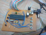
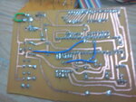
here are my circuits, after i program in still unable to work
DSC00325.jpgDSC00324.jpg
 

Hi,

Can see your component side clearly, but the pcb side is very blurred.

Some of the tracks look very close together , almost touching, have you checked them for shorts with you ohm meter ?

Below is a basic circuit to run a 877A, from what I can make of your board , you seem to have that.

Assume you have some leds at the end of your output cable, are they are wired correctly ?
Also I do not know what leds you are using, the Pic chip can only supply 25ma per pin, with a maximum load though the chip of 250/300ma.
If you have too many leds running too bright, then the pic and regulator will overload / heat up before expiring.


As you can see from the picture if you leave your display unconnected you can check the output ports with your voltmeter for high or low.

- - - Updated - - -

Hi,

Lesson here, do not rely on simulations, there IS still an error in the code that stops it working on actual hardware.

Change this line of Config code to include the _LVP_OFF, it then does run on hardware as well as simulation.

__CONFIG _CP_OFF & _WDT_OFF & _HS_OSC & _PWRTE_ON & _LVP_OFF
 

Attachments

  • ScreenShot001.jpg
    ScreenShot001.jpg
    34.1 KB · Views: 79
hi wp100, actually what is _LVP_OFF?
actually i am building the 4x4x4 LED, LED is super bright green LED

- - - Updated - - -

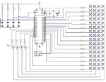
her are my schematic

led.JPG
 

hi wp100, actually what is _LVP_OFF?
actually i am building the 4x4x4 LED, LED is super bright green LED

- - - Updated - - -

her are my schematic

View attachment 75421


IF LVP is on, you cant use RB3 pin, its dedicated for Low Voltage Programing. It should be grounded for proper operation else the controller will reset ( even if we touch the pin which is left unconnected), if you connect RB3 to VCC it will go for programming. Or you should disable LVP for using RB3 for general purpose.

Vishal
 

hmm, i will try and see
if LVP is off and still cant run the program, what is happening,
from i measured from power supply to pic is 5v, then all component got voltage even my LED also measured 5v, but why unable to light up also
 

The drive to the transistors from RC0 to RC3 should be high but the other pins should be low or no current can flow through the LEDs.

wp100 is absolutely correct about LVP, if you are using high voltage to program the PIC you should turn LVP off in the source code and recompile the code again or it will not work.

I can't read the resistor values in your schematic but you might consider connecting a capacitor between MCLR and ground (across the switch) to hold the PIC in a reset state until the power supply and clock have had time to stabilize. Given that you are switching relatively high current, it might be a good idea to add additional decoupling capacitors across VSS and VDD too, I suggest 10uF in parallel with 100nF.

Brian.
 

Hi,

Your program code starts by turning on 16 to 20 of the leds, exactly how much power each of your super bright leds are taking is hard to know, but 20 leds will probably exceed the current handling of the pic chip / ports and perhaps drag down your PSU.

I don't know if the circuit is your own design, but it looks typically like a led array to be use for Charlieplexing, the key point is that the leds are only each turned on for a few milli-seconds which considerably reduces the total current used.
You are turning them on all on for seconds, so using full power.


You do not say if your PCB / circuit has run anything else other than this led program.

In view of your problems it would seem wise to disconnect the led array and first test your whole ciruit with a simple one led flasher program.

If thats ok, then try your program again, but still leave the main leds disconnected, just try and monitor the pics outputs with a voltmeter to see if they are working properly.
 

I think you need to try _BODEN_OFF too....mostly your voltage is not sufficient to drive the PIC....

Good Luck
 

Hi,

Your program code starts by turning on 16 to 20 of the leds, exactly how much power each of your super bright leds are taking is hard to know, but 20 leds will probably exceed the current handling of the pic chip / ports and perhaps drag down your PSU.

I don't know if the circuit is your own design, but it looks typically like a led array to be use for Charlieplexing, the key point is that the leds are only each turned on for a few milli-seconds which considerably reduces the total current used.
You are turning them on all on for seconds, so using full power.


You do not say if your PCB / circuit has run anything else other than this led program.

In view of your problems it would seem wise to disconnect the led array and first test your whole ciruit with a simple one led flasher program.

If thats ok, then try your program again, but still leave the main leds disconnected, just try and monitor the pics outputs with a voltmeter to see if they are working properly.

as what i search is using 3 - 4 voltage, and the resistor connected b4 Led is 180Ohms.
my Circuit do not run the function other than led program
 

Hi,

If you can, try running this simple Flasher program, .asm and the ready to run .hex file attached.

Suggest you disconnect your led array if possible or at least disconnect the +5v going to the 4 transistors.

I have run the program on my chip ok , so know it works fine.

You can connect a standard led to PortE,0 as shown or use your voltmeter on that pin any watch it pulse from 0v to +5v.
Depending of the crystal frequency it will flash for 1 second at 20 mhz down to 5 seconds at 4 mhz.

Let us know if that works, if it does not then your hardware must be at fault or the chip is not being programmed properly.
 

Attachments

  • FLASH.ASM.rar
    41.4 KB · Views: 45

HELLO

First Sorry in writing in CAPITAL becuase I see a small bug which is screwing up everything.

PLEASE CHECK YOUR INPUT CONECTOR POLARITY. I THINK IT IS REVERSE AND GOING TO WRONG PIN OF REGULATOR.

Thankyou.
 

Status
Not open for further replies.

Similar threads

Part and Inventory Search

Welcome to EDABoard.com

Sponsor

Back
Top