Continue to Site

Welcome to EDAboard.com

Welcome to our site! EDAboard.com is an international Electronics Discussion Forum focused on EDA software, circuits, schematics, books, theory, papers, asic, pld, 8051, DSP, Network, RF, Analog Design, PCB, Service Manuals... and a whole lot more! To participate you need to register. Registration is free. Click here to register now.

Circuit to generate 2 non-overlapping clocks in GHz range

Status
Not open for further replies.

shockingshockley

Member level 1
Joined
Dec 11, 2010
Messages
33
Helped
0
Reputation
0
Reaction score
1
Trophy points
1,286
Activity points
1,611
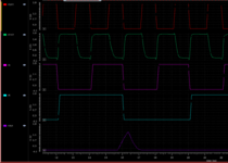
Hello. I am working for a circuit to generate 2 non-overlapping clocks in GHz range. However, the circuit only works in the MHz range. What are the probable reasons why it does not work? Or do you have any suggested circuit for this purpose? TIA
 

Hi,

You don't show a schematic, nor a code, nor any simulation results, nor do youcsay which hardware you use.
What is your idea? How can we help?

Klaus
 

Hi,

You don't show a schematic, nor a code, nor any simulation results, nor do youcsay which hardware you use.
What is your idea? How can we help?

Klaus
Sorry, here is the schematic of the inverter and simulation result. I have a triangular output instead of the pulse output.
 

Attachments

  • 239992277_2604680519835378_7103690605606648778_n.png
    239992277_2604680519835378_7103690605606648778_n.png
    22.9 KB · Views: 120
  • 240546720_519762205784374_6861059120685336165_n.png
    240546720_519762205784374_6861059120685336165_n.png
    50.3 KB · Views: 122

Hi,

I shouldn't be here - my speciality is spectaculary bad analog design full of hobbyist mistakes, but still, in case the main comment is useful...

I'm used to seeing non-overlapping clock generators done with logic gates of varying complexity, this being the typical simplified one you'll be familiar with:

nonoverlapping clock generator typical.JPG


The other day, not seriously looking into discrete non-overlapping clock generation using standard logic and BJTs, I noticed that the trailing edge of both signals needs to be shut down by its rising complement, otherwise they overlapped (throwing capacitors at the circuit does not solve the problem, just displaces it in time) - I see that yours also overlaps in that way in your space invaders picture. In my wayback machine cartoon you can see what I mean. I doubt the wayback circuit even works in reality, btw, and the (1uF) risetime delay caps have to be selected based on the actual clock speed, it's a NRND circuit, it's just to show what I'm referring to:

nonoverlapping clock generator discrete.JPG


How you'd get your circuit to GHz speed, no idea, surely that's related to MOSFET capacitances?
 

Hi,

It depends what the person who started the thread is doing. Maybe it would be better classed under 'Analog Circuit Design' or perhaps 'Analog Integrated Circuit (IC) Design, Layout and Fabrication', or possibly 'RF Microwave, Antennas and Optics'. I have no idea as I do not know what their end goal is.
Definitely not "RF Microwave, Antennas, and Optics." "Analog ICs" could work in principle, but we really need a separate space for digital circuits, layout, logic gates, and logic solutions, and nothing looks obvious in the top-level categories. Analog guys are all about PLLs, power supplies, bandgaps, antennas, transmission lines, etc. In digital, we generally try to pound all analog signals into square waves or flat lines, and pack everything as densely as possible. This is relevant to ASICs far more than to Analog ICs.

I've seen a few digital circuits/gate solutions appear in "Digital Signal Processing," but that forum is primarily about the math. Also in "Elementary Electronic Questions," but these concerns are beyond elementary.

It is a distinct subset of ASIC design methodology, but I'd much prefer to have a category for "Digital Circuits and Logic."

On a related note, where would "Mixed Signal Design" belong?
 

Status
Not open for further replies.

Part and Inventory Search

Welcome to EDABoard.com

Sponsor

Back
Top