joelalfuerto
Junior Member level 3


---------- Post added at 16:55 ---------- Previous post was at 16:47 ----------
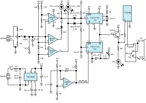
Here is the simple description of the circuit:
The circuit in Figure 1 protects the ac line against disturbances.
It operates by switching off the power supply upon
detection of undervoltage or overvoltage conditions. The
c i rcuit thus protects refrigerators, washing machines, air
conditioners, and other appliances from permanent damage
that could accrue from working outside their specified
power requirements. The problem assumes particular
importance in underdeveloped countries or regions where
the ac-supply network is incorrectly configured, and the
voltage frequently drops to levels low enough to damage
coils and motors. When the ac-line voltage returns to its
nominal level, the circuit automatically resets a switch and
reconnects the line voltage.
The input stage contains a voltage divider, which you can
adjust with the 1-kV potentiometer. The circuit incorporates
a rectifying diode and a 10-mF storage capacitor that
provides lowpass filtering to stabilize the ac-supply voltagecomparison
level. You should adjust the potentiometer
such that the normal condition of the ac supply, 220V, corresponds
to a 1.97V voltage-comparison level. Three comparison
voltages verify the ac-line status, using resistive
voltage dividers. The voltages correspond to a 10%-undervoltage
warning, a 20%-undervoltage failure level, and a
20%-overvoltage failure level. These comparison voltages
correspond to ac-supply voltages of 198, 176, and 264V,
r e s p e c t i v e l y. Three sections of the quad open-collector
LM339 comparator convert these voltage thresholds to digital
signals.
The 10%-undervoltage warning condition turns on a yellow
LED. Failure conditions turn on a red LED and trigger
the dual retriggerable monostable multivibrator, IC2. The
output of the first ,IC2A, is narrow and serves to define a time
window that prevents sudden transient disturbances from
triggering IC2B. Consequently, if the ac-line voltage quickly
returns to its nominal condition, the circuit does not disconnect
the load. The output pulse width of the other
monostable, which you can adjust via the 50-kV potentiometer,
defines the time the load remains disconnected
after the return of the nominal ac-line voltage.
An RC delay line ensures that when the second monostable
triggers, the first one has already activated its Clear
input. The fourth comparator of the LM339 produces a
high-frequency square wave that continuously retriggers
the monostable while the fault condition is present. To save
power from the regulated 5V supply and to allow use of this
circuit to protect high-current equipment, you should use
an output relay whose coil control comes from the powersupply
rail. A TIC206D triac, gated by the monostable,
switches the relay coil. A green LED indicates that the acline
level is normal and the relay’s contact is closed. IC1, a
Harris HV-2405E offline regulator, supplies the regulated 5V.
Because this circuit connects to the ac line, you should use
an insulated enclosure, and take care in testing the circuit.

