pgsabel
Newbie level 6
Hi everyone,
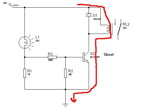
Exists some circuit that allows to indicate when a light bulb of 24V burns in the proper circuit that it is installed?
I would be pleased if you help me here.Thanks
Exists some circuit that allows to indicate when a light bulb of 24V burns in the proper circuit that it is installed?
I would be pleased if you help me here.Thanks