Continue to Site

Welcome to EDAboard.com

Welcome to our site! EDAboard.com is an international Electronics Discussion Forum focused on EDA software, circuits, schematics, books, theory, papers, asic, pld, 8051, DSP, Network, RF, Analog Design, PCB, Service Manuals... and a whole lot more! To participate you need to register. Registration is free. Click here to register now.

Circuit design help!

Status
Not open for further replies.

pclaptop

Newbie level 3
Joined
Feb 22, 2015
Messages
4
Helped
0
Reputation
0
Reaction score
0
Trophy points
1
Activity points
52
I'm picking any engineer/small~circuit~design brain for some help!

I want to create two panels(with two separate pcb's) set 3-4 feet apart, that house 10 piezoelectric transducers each that will act as an intrusion deterrent when an alarm condition exists.

These transducers operate at 2.5khz sine or square wave but need a signal generator circuit to supply that waveform to operate. I would like to just apply 12vdc to the 10 piezo's but I think that would create "fried chicken"!

Basically I have a 12vdc battery source that is solar charged(re-charged) at a location where there is no electricity.

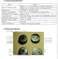
I believe all I need is a 555/556 timer circuit with an open collector xsistor(??) to handle the output, but that's as far as my design knowledge goes. Attached you will see a spec sheet for the transducers and a physical picture of the devices themselves. I got a deal on 90 of them.


Also, this circuit I found Googling but I don't know . . .
1) if it will handle 10 of the Piezo's and

2) I want create a very offensive warbling at 2.5khz (hence the 556 timer, one 555 to set at 2.5khz and the other to pulse?) to create a delay or offset the second panel frequency.

http://www.electronicecircuits.com/electronic-circuits/555-variable-frequency-square-wave-generator

Any thoughts suggestions designs ideas pointers?

thanks in advance, chris
 

Unfortunately, those piezo transducers do not work as you think. When you put DC across them, the element bends one way, if you reverse the voltage it bends the other way. They are not damaged if you leave the DC voltage present but neither do they produce any sound. To make the warbling you have to alternate the voltage polarity fast enough to make the element bend back and forth to produce the sound pressure waves. Due to their construction, they will only work at one frequency so you also have to be careful to keep the frequency very close to 2.5KHz, if you move more than a few hundred Hz either side of 2.5KHz the volume will drop dramatically.

The next problem is making them warble, if you drive them at 2.5KHz they produce a constant 2.5KHz tone which although unpleasant is just a whistle. You need a second oscillator to add the warble to the tone. You can do it two ways, either frequency modulate the tone so it goes slightly higher them lower in pitch (bear in mind the frequency/volume warning) or you can interrupt the tone so it chirps on and off quickly. Frequency modulating (FM) is probably the most annoying but interrupting it (AM) is more power efficient. Either way the second oscillator runs at much lower frequency, somewhere in the 10Hz to 20Hz reegion is probably best.

You basically need two oscillators, one at 2.5KHz and one at say 10Hz, they can both be NE555 or equivalents which are very inexpensive or you can use a 556 which is basically two NE555s in one package. You will need at least two transistors to drive the piezo devices because 20 of them will try to draw more current than an NE555 can produce by itself. To get maximum volume you need to step up the voltage to nearly 30V which is not possible directly from a 12V battery but you can use a step-up transformer to do it. You put more current in the primary in exchange for more voltage out at the secondary, this is the method used in commercial alarm systems.

Brian.
 
Did you see the low output sound level at the distance of only 10cm? A burglar or a bear will need to wear the piezo transducers on his ears to be deterred.

With a 9V squarewave the output at 10cm is 85dB which is not loud. Two will produce 88dB, four will produce 91dB and eight will produce 94dB. Ten will produce about 95dB and twenty will produce 98dB.
At a distance of 20cm the sound from twenty transducers will be 91dB. At 40cm it will be 86dB and at 80cm it will be only 80dB. At 320cm the burglar is still pretty close and the sound level will be only 68dB.

The array of transducers will make a narrow beam of sound, it might not be what you want.

Two panels of transducers only 3-4 feet apart might be a narrow hallway. Then an intruder beside both panels will be about 1 foot (30cm) away from both panels. The sound level will be 90dB then he moves a few inches and it is much less.

Since the piezo transducers resonate at only one frequency then warbling the frequency will simply make the sound level go up and down, mostly down.
 
I used this handy oscillator (two of them) to create a beeping alarm.

beeper oscillators 1Hz and 2 kHz using 4 invert gates.png

There is an inexpensive IC which contain 6 inverter gates. (4049 or 4069 CMOS hex inverter.) Your project will need 7 or 8 of these.

(Please disregard the switching arrangement at the bottom. It's only there to begin stable oscillations in this finicky simulator.)

Connect the disconnected diode, from the output of the slow oscillator to the input of the fast oscillator. (You may need to reverse its orientation, depending.) This arrangement enable and disables the beeper at a rate of 1 Hz.

Your master on-off signal will be applied from the left, possibly through a diode (shown). When it conducts, it disables the slow oscillator.

Your piezo device can be connected as the load. Or as an alternate, experiment with putting the piezo in place of C2. If you are lucky it will lock in its own resonant frequency automatically.
 
Status
Not open for further replies.

Similar threads

Part and Inventory Search

Welcome to EDABoard.com

Sponsor

Back
Top