Continue to Site

Welcome to EDAboard.com

Welcome to our site! EDAboard.com is an international Electronics Discussion Forum focused on EDA software, circuits, schematics, books, theory, papers, asic, pld, 8051, DSP, Network, RF, Analog Design, PCB, Service Manuals... and a whole lot more! To participate you need to register. Registration is free. Click here to register now.

Choice of L(res) C(res) in LLC converter?

Status
Not open for further replies.

cupoftea

Advanced Member level 5
Joined
Jun 13, 2021
Messages
2,663
Helped
54
Reputation
108
Reaction score
116
Trophy points
63
Activity points
13,999
Hi,
I hear..
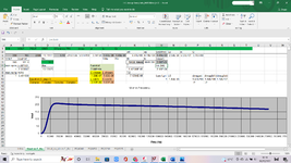
....that in an LLC converter, L(res) and C(res) should be chosen such that SQRT(Ls/Cs) = ~1.5 * "Load resistance".

...Presumably thats the "referred AC load resistance", ie 8* (Np/Ns)^2* R(out) / (pi^2)?

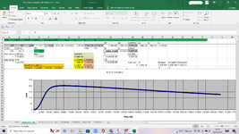
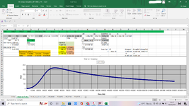
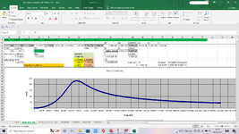
The thing is, when you do this, you end up with your intended operating frequency being very near to the peak of the gain curve....ie, the "peak of doom"...that frequency above which, you go into the dreaded "capacitive region"....so it feels more coMfortable to make SQRT(Ls/Cs) of a value nearer 1.....is this OK?

So is there any leeway in this choice of Lres and Cres?

Presumably its all about short circuit currents and overload?
 

When current is switched on, the series LC shapes current flow into a sine:

1)The inductor smoothes its upward rise in the shape of the familiar curve.

2) Current reaches a plateau, or rather it would if the inductor were the sole component in the path.

3) The capacitor has been charging, and now it restricts current flow.

4) Current drops to zero in the shape of the familiar curve).

5) Sine is complete.

-----------------------------------------------------------------

L & C values determine resonant frequency.

Too small C value charges rapidly, shutting down current and shortening the sine shape, effectively raising frequency.

Too large C value charges slowly, lengthening and distorting the sine shape.


L & C ratio has to do with the level of current available to 'operate' them. In other words to generate desired voltage swings. Large C value tends to inhibit oscillations starting due to greater current required to operate it. In some cases large C value causes oscillations to fade entirely.

At times I ran simulations of series LC shaping a square wave into a sine, the values must be customized to the load and desired frequency.

If switching comes from an external clock, I must select L & C values so the sine shape fits within the duration of clock pulse. The aim is to make the capacitor close off current at the same time the pulse ends.
 
Hi,
Why are high values of resonant capacitor frowned upon in LLC converters? I mean, why does SQRT(L/C) have to be above a certain value?
(Where L = resonant inductor; C = resonant capacitor)
Why are LLC converters with a low value of SQRT(L/C) deemed to be less able to handle short circuit output? There is no logical reason for this?
..._..._..._
The four attached jpegs show three cases of Half Bridge LLC design component values.

This LLC has 390vin, 2kW, 180Vout.
In all cases, Resonant frequency is set to 70kHz.
In all cases, the NP/NS is 1:1
In all cases, Transformer L(mag) = 1.45mH

There is also an external L(mag) in each case.

Case 1…L(res) = 10uH
Case 2….L(res) = 20uH
Case 3….L(res) = 37uH
Case 4…L(res) = 5uH

…..In the 4 above cases, the C(res) value was adjusted so that f(resonance) is 70kHz.

In Case 1, the External magnetising inductor could be advantageously increased to 200uH, and as shown, still keep the 70kHz operating point well above the “peak of doom” (lower resonance frequency).

In case 2, the External magnetising inductor, unfortunately had to be reduced to 150uH, in order to keep the “peak of doom” far enough away from the intended frequency of operation

In case 3, the External magnetising inductor, unfortunately had to be reduced down to 60uH , in order to keep the “peak of doom” far enough below the intended operating frequency.

In cases 2 and 3, the ETD59 offtheshelf gapped core was seeing high delta B in the core, due to the lower inductance. A bigger gapped core could not be chosen, since no offthe shelf gapped cores exist above ETD59 in size.

As such, case 2 is chosen, and has L(res) = 10uH and C(res) = 517nF. Case 2 is very “flat”, but no problem with this is seen.

Case 4 looks great, and allows an L(mag) increase to 300uH, and still keep the peak of doom well away from the intended frequency of operation…however, it will be difficult to wind a whole number of turns onto an offtheshelf gapped ETD59 core and get the inductance equal to 5uH, or even near it…so this case 4 could not be chosen. If a custom gapped core could be used, then case 4 would be ok, but custom gapping is too expensive.

(actually, in all the above cases, the intended operating frequency is slightly above 70kHz, as you can see…..ie, the operation has been chosen to be slightly above resonance, as this is deemed to have good properties with regard to output short circuit protection?)
 

Attachments

  • 5uH Lres.png
    5uH Lres.png
    193.7 KB · Views: 84
  • 10uH Lres.png
    10uH Lres.png
    197.6 KB · Views: 79
  • 20uH Lres.png
    20uH Lres.png
    201.1 KB · Views: 85
  • 37uH Lres.png
    37uH Lres.png
    197.8 KB · Views: 79

It is normal to consider what happens when you short the Tx sec - and size the Lseries res to keep the currents down to where the mosfets won't blow up during the time it takes for the current limit to function, having got there, the freq and the L set the size of the C.

A "peakier" curve gives better control over freq - but the rms currents are not minimised for the design -

Designing for min ave rms currents in the pri side and for the criteria mentioned above re sec side shorts - alongside a resonable freq range of control ( often 100kHz - 250kHz type range, i.e. 1: 2.5 ) - always gives a similar ( engineering) solution of larger L than you seem to be considering ...
 
It is normal to consider what happens when you short the Tx sec
Thankyou for coming forward with this...yes , in fact, i ran the attached LTspice simulation, which compares short cct behaviour with bigger and smaller Lres values, and to be honest, they arent that different.......(37uH and 20uH).....admittedly the 20uH one does go to a higher current upon short cct......however, it rises quicker initially, which we didnt like too much....either way, we are hoping our current transformer will catch this before it happens.

But yes, i kind of intrinsically agree that a bigger Lres will limit the short cct current more......but in the sim it wasnt that much worse.....and given that our CST shoudl catch it, i wonder if we can get away with smaller Lres (and thus bigger Cres)?
Bigger Cres does certainly ease the design for our hammered wallets........it means we can use offthe shelf ETD59 gapped cores for the external Lmag.

I usually find with LLC....it always comes down to sizing everything so we are sufficiently far enough away in frequency from the "peak of doom"....(as you know, P.O.D. = that freq where reducing frequency then reduces vout and gives unwanted capacitive mode)
 

Attachments

  • HalfbridgeLLC_70khz_LC compare.zip
    3.5 KB · Views: 86

SQRT(L/C) describes L:C ratio.
High L:C ratio has an automatic effect to limit current, as compared to low L:C ratio.

Conversely if available current is low, then high L:C ratio assists toward starting and sustaining resonant oscillations.

But then large L tends to add bulk and expense. So I picture an inventive designer somewhere saying 'How can we use a smaller inductor and still get desired performance from it? Maybe by adding another inductor (LLC) or capacitor (LCC).'

To reach success requires extra design effort, because of various unwanted effects which pop up along the way.

I don't claim to understand this informative TI paper which you may already be aware of:

Designing an LLC Resonant Half-Bridge Power Converter

ti.com/seclit/ml/slup263/slup263.pdf

And it was mentioned in previous Edaboard discussion:

edaboard.com/threads/llc-converter-transformer-design.361112/
 
Last edited:

Thanks BradtheRad, thats a great App note in your post #6....mind you , on page 6 it states..

(During operation at above the resonant frequency)....The rectifier diodes are not softly commutated and reverse recovery losses exist...
[UNQUOTE]

...As we all know, this is totally incorrect, and i'm sure we've had the comfirmatory discussion before on this forum.
(sorry to be pinickity though, its otherwise a great document)
 

always measure the rms currents for various solutions to your LLC design,

every extra amp causes heating in all the pri side power components

higher L/C ratio's give lower rms

it's really that simple
 

Thanks, i also find when the load is heavy, in the calc doc, i need to increase C(res) and reduce L(mag) in order to stay well away from the "peak of doom" frequency.
 

Thanks, yes i agree, and i also like to be sure that the freq of operation is well away from the peak of doom in case of capacitor tolerances etc......and also, i actually, possibly wrongly, feel that in overload etc, if my operating point is already far from the peak of doom, then i'm less likely to suffer quite so major grief in faults like overload etc...but this might just be me imagining benefit when there is none?
 

Status
Not open for further replies.

Part and Inventory Search

Welcome to EDABoard.com

Sponsor

Back
Top