Continue to Site

Welcome to EDAboard.com

Welcome to our site! EDAboard.com is an international Electronics Discussion Forum focused on EDA software, circuits, schematics, books, theory, papers, asic, pld, 8051, DSP, Network, RF, Analog Design, PCB, Service Manuals... and a whole lot more! To participate you need to register. Registration is free. Click here to register now.

Chinese Laser Diode Driver fault - Reverse eng. to tune

Gigillo74

Member level 3
Joined
Aug 24, 2007
Messages
61
Helped
0
Reputation
0
Reaction score
1
Trophy points
1,288
Location
Bologna - Italy
Activity points
1,662
Hi all,
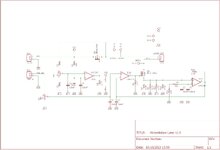
i'm going to use the driver shown in attached image and i've a laser fault due to strange driver functionally.
So i've decided to do rev.eng. of this driver to know how it work.
Immagine.png
Immagine1.png

I've just noted there is no current feedback on power mosfet and the current feedback from opamp is connected on pin n. 5 (feedback on voltage regulator IC)
Someone can explain me this strange issue?
Thank You.
 
The schematic has errors, e.g. flipped IC1.1 and IC1.3. Also R13 is connected to VDD rather than VCC.

Obviously laser diode current is regulated by varying VDD.
 
Minor schematic error on D1 is on the output, before 5k1 with open loop OA gain on current sense of 0.01 Ohm. Couple other errors.

When regulated Vfb = 0.925 V. The IC2 regulator raises voltage and thus Laser output current But raising R13 trimmer to Vcc makes loop faster and biased towards off with trimmer R near Vdd output. Not sure which direction wiper is normally goes from pin 1 to 3. in CW direction.

Basically the regulator output has Av= 1+R2/R1 and the Vfb Ref is 925 mV so the output is near 1.8V when R1~=R2 which is a Laser off condition.

R13 trimmer controls the maximum laser voltage unless there is overshoot from power up.
R2 trimmer controls output peak current and is very sensitive.
TTL controls the PWM off cycles.


1697320910228.png
1697322927028.png
 
The schematic has errors, e.g. flipped IC1.1 and IC1.3. Also R13 is connected to VDD rather than VCC.

Obviously laser diode current is regulated by varying VDD.
Hi FvM, thank you for error analysis.
This one is sch with error correction.
sch.jpg

--- Updated ---

Minor schematic error on D1 is on the output, before 5k1 with open loop OA gain on current sense of 0.01 Ohm. Couple other errors.

When regulated Vfb = 0.925 V. The IC2 regulator raises voltage and thus Laser output current But raising R13 trimmer to Vcc makes loop faster and biased towards off with trimmer R near Vdd output. Not sure which direction wiper is normally goes from pin 1 to 3. in CW direction.

Basically the regulator output has Av= 1+R2/R1 and the Vfb Ref is 925 mV so the output is near 1.8V when R1~=R2 which is a Laser off condition.

R13 trimmer controls the maximum laser voltage unless there is overshoot from power up.
R2 trimmer controls output peak current and is very sensitive.
TTL controls the PWM off cycles.
Hi Tony,
thank you for you support to explain how circuit works.
I think two separate block are better than chinese solution.... one that cab regulate maximum output voltage and another one (in series after first) that make current loop with an opamp. I've try to design this idea but i'm not sure how add PWM input to modulate output current. Please, take a look on this sch. :)

Immagine.jpg
 

Attachments

  • Immagine.jpg
    Immagine.jpg
    429.8 KB · Views: 60
Last edited:
The PWM duty cycle is a linear power control, iff ;
1) there is no significant overshoot for turn-on. This requires proper stability design and verification.
2) minimum pulse duration determines dynamic range of PWM >> than regulator on>off>on time
3. The PWM cycle time is much faster than the thermal response of the junction.

  • As I recall the best Laser control system uses optical sampling inside Laser and linear current feedback.
  • Using RC filtering adds to latency and overshoot unless critically damped.
  • The peak current is the most critical parameter to control for reliability because overshoot square law for power and this design will have overshoot.. You are not measuring peaks. Recall your 1st Sch had diode in wrong position.
  • The mean optical power is most important for linearity will change with temperature and current.
  • So approximations depend on your error tolerance and margins for Laser MTBF.
So before you try to design it, 1st analyze the Laser MTBF and linearity problems of PWM
and specify your assumptions, parameters and error tolerances.

Remember the Laser MTBF will reduce 50% for every ~10'C rise in junction temperature ( Arrhenius Law) But what is Laser temperature vs current? What is rating spec ? __ h at __A?
Hi Tony,
thank you for suggestion.
The circuit would drive a Nichia model NDB7875-E 9mm laser diode.
Below the datasheet.
 

Attachments

  • NDB7875-E.pdf
    79.4 KB · Views: 49
So this is a learning experience with a faulty laser and you want to make the driver more reliable with your own design?

Is the LD burnt out or the driver?

Was this operator error in exceeding ratings or design flaw or from power On then overshooting after working before with slow turn-up?

This is a good experience to learn from other failures but this laser is only 100mW and has no internal photodiode. If you want more power or a better design, you might want to buy a more useful 4W to 10W Laser for $100 with a tuneable focus, large heatsink, fan, and better reliable drive with external PWM linear control of power to burn wood or plastic. Then learn from the better design.

FWIW There exists xx W hand-held IR/R lasers for acupuncture, etc for $4k with a smart display/controller.

BTW Nichia is one of the best OE parts in Japan but the factory could be in China.
The driver PCB, package designs may be of Chinese origin, and some are good in mass production, if mature.

Because the Lasing effect is very non-linear with high Rs until the lasing threshold then very low Rs and wide threshold tolerances. This also has hysteresis and very non-linear, regulator latency parameters are critical for overshoot design control to regulate pulsed current.

Many LD regulators just have one 10:1 trimpot so their control method might be more linear and not need the trimpot for voltage limit relative to each LD threshold. But overshoot can be a critical failure for LD's.

So review what is your desired outcome and share.
 
Last edited:
So this is a learning experience with a faulty laser and you want to make the driver more reliable with your own design?

Is the LD burnt out or the driver?

Was this operator error in exceeding ratings or design flaw or from power On then overshooting after working before with slow turn-up?

This is a good experience to learn from other failures but this laser is only 100mW and has no internal photodiode. If you want more power or a better design, you might want to buy a more useful 4W to 10W Laser for $100 with a tuneable focus, large heatsink, fan, and better reliable drive with external PWM linear control of power to burn wood or plastic. Then learn from the better design.

FWIW There exists xx W hand-held IR/R lasers for acupuncture, etc for $4k with a smart display/controller.

BTW Nichia is one of the best OE parts in Japan but the factory could be in China.
The driver PCB, package designs may be of Chinese origin, and some are good in mass production, if mature.

Because the Lasing effect is very non-linear with high Rs until the lasing threshold then very low Rs and wide threshold tolerances. This also has hysteresis and very non-linear, regulator latency parameters are critical for overshoot design control to regulate pulsed current.

Many LD regulators just have one 10:1 trimpot so their control method might be more linear and not need the trimpot for voltage limit relative to each LD threshold. But overshoot can be a critical failure for LD's.

So review what is your desired outcome and share.
Hi Tony,
thanks for the tips.
The problem I had was that the driver, during operation with the laser I indicated to you but in the 3W version, stopped working. Since it was behaving strangely when I tried to adjust the operating voltage and the necessary current, I thought it was time to understand how it works and, possibly, try to modify it to make it work properly. Then I thought that a separate control of voltage and current would be qualitatively better and I've designed the circuit with the opamps I had posted. Now I would like to use the laser with a driver that allows me to give it the right settings in terms of current and voltage. Thank you.
I think the separate Vreg has too much latency to give a stable operation with the hysteresis of current and will create an Astable operation with overshoot. I don't know how to choose a critical voltage for Vreg but it will be such the current regulator has a minimum voltage drop. It may need to be thermally compensated with the Laser junction temp just like Class AB bias. The feedback needs to be limited so that the Vreg range is limited to prevent windup overshoot.

Excess heatsinking is critical, meaning high thermal conductance and velocity to reduce the junction thermal overshoot. ( Arrhenius Law effects ) Then a 5W Laser tends to look like a 100W CPU heatsink.

Also reverse laser voltage needs to be examined from any inductive flyback condition.

I found a block diagram for basic design.
1697569989220.png


I think the TTL PWM modulation should be between 2% and the setpoint and not On / Off. That would be slow and unstable.

Optical feedback is ideal but hard to make stable externally for thermal mechanical reasons but ideal for linear mode operation, so internal sensors are preferred.
1697570333352.png

--- Updated ---

here are some simple old designs, mainly low-power linear current regulation http://www.walshcomptech.com/repairfaq/sam/laserdps.htm#dpstoc
--- Updated ---

Here are some high power LDs with PDs. http://www.roithner-laser.com/ld_pulsed.html
 
Last edited:

LaTeX Commands Quick-Menu:

Similar threads

Part and Inventory Search

Welcome to EDABoard.com

Sponsor

Back
Top