Continue to Site

Welcome to EDAboard.com

Welcome to our site! EDAboard.com is an international Electronics Discussion Forum focused on EDA software, circuits, schematics, books, theory, papers, asic, pld, 8051, DSP, Network, RF, Analog Design, PCB, Service Manuals... and a whole lot more! To participate you need to register. Registration is free. Click here to register now.

Check my circuit for driving a motor in both directions

Status
Not open for further replies.

Pheetuz

Full Member level 3
Joined
Feb 12, 2010
Messages
162
Helped
21
Reputation
42
Reaction score
19
Trophy points
1,298
Location
Brighton
Activity points
2,835
Missing something???

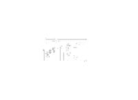
Hi there, I have built this circuit to drive a motor in both directions.
The PIC gives out either a 1 or a 0 to the relay to control direction and it also gives out PWM to the AD22057 N - I have just used this particular package in this cicuit as a means on representing A3120 IC that i am using to drive my MOSFET, this is because the version of software i am using doesnot have the chip within it and i was pressed for time to create a new component.

Each individual part of this circuit has worked fine for me when i have tested it individually - i.e the relay section, the pic, the mosfet section etc... But when i have put it altogether on a breadboard it has stopped working, in one case the PIC has even stopped working, I have been thinking its probably just due to it being made on breadboard but i just wanted to check that i am not missing anything vital ???

Many thanks.

/Pete


Missing something???

The component values in the picture arent the ones that I am using.

R1 = 3k
R2 = 10
R3 = 220K
R4 = 1M
R5 = 5K

C1, C2 = 33pF
C3, C4, C7, C6 = 100nF
C5, C8, C9 = 100uF
Also, the motor is connected between J1 and J2.

Many thanks.

/Pete

Added after 5 minutes:

I have also just noticed that this isnt my final design, the final design is the same but the chip and main power line both have decoupling capactiors of 100uF.

Thanks again.
 

Re: Missing something???

Assuming the amplifier is wired correctly:

1. D1 is backwards
2. C3,4,6 & 7 should be nF not pF
3. Pins of the PIC shouldn't be floating
4. You are using a 1A regulator to supply 600µA (not wrong but inappropriate)
5. Unless you are using a weird crystal, C1 & C2 are about 5x the correct values.
6. C5,8 & 9 are connected backwards.
7. You are only just providing enough voltage to turn the FET on. Make R2 smaller and R3 larger.
8. Q2 drain and source pins are swapped.

Other than that it looks OK :|

Brian.
 

    Pheetuz

    Points: 2
    Helpful Answer Positive Rating
Re: Missing something???

Hello.

Thanks for looking over the circuit, the values that i used in the picture arent the ones that i was actually going to use, i realise now that i should have posted them in the original post instead of in a reply.

Did you have a look at the values i had put in the reply? Are the more the sort of values you would expect??

Also, are you certain that D1 is backwards, just thats how ive always used them??

Whoops about drawing the capacitors backwards, dont worry though, i didnt put them in the wrong way when i was testing the circuit =P

Thanks again :)

/Pete
 

Missing something???

Hi Pete,
OK, that you didnt build it falsh in, but the "Pol-Caps" and FET (+ things of Brians notes) are to change_right to drow!
Electrolytics +polarity isnt to fill as in your schema_filled must be at negative polarty!
Gate connection of a MOSFET is at S and not at D to drow...
K.

Added after 19 minutes:

Dont forget pls; U4 as symbol is wrong! (or very-very unconventional:-(()
I afraid that these is not funtioning too...
Anyway: suppl-pin & GNDs are changed and so on.

I missed the protection diode on your Motor/Fet too!!:-(
 

Missing something???

What is the A3120? I cannot find it anywhere.

Keith.
 

Missing something???

Hi Keith,
Thes is maybe nearby to the motor protector diode:)...
K.
 

Missing something???

karesz

Sorry, I was not clear. I can see where the device is on the diagram - I cannot find a data sheet to know what it is.

Keith.
 

Missing something???

:)
No problem, but for me is a problem to see it, where can you see/find it on the circuit diagram pls?
K.

Or is it a power amp? ...The TPA3120D2 is a 25-W (per channel) efficient, 10 V to 30 V Class-D audio power amplifier
 

Missing something???

Well, it is very confusing because he has drawn a AD22057 where the A3120 should be. That is why the pinout for the AD22057 is crazy - it isn't really that device! I don't know how anyone can help check it - there are too many unknowns and too many chances of an error due to the confusing drawing. Maybe what Pete built isn't what he thinks he built?

Keith.
 

Missing something???

Tnx;
and I agree with you!
Have nice time!
K.
 

Re: Missing something???

lol, sorry for the confusion guys, just that i didnt have time to make the component so i just used the first 8pin dil chip that i could find and wired it up correctly, im certain that part of the circuit is correct, its just the other bits i was wondering about.

Anyway, thanks for having a look both of you :)

/Pete
 

Missing something???

I think betwixt covered the obvious problems. It might be worthwhile checking them again to make sure they are just drawing problems not building problems - particularly D1.

Keith.
 

Re: Missing something???

D1 is correct in the current diagram. It should be cathode to supply, symbolically with the arrow toward the supply line. In normal operation is should NOT conduct, it is there to trap the reverse kick from the relay magnetic field collapsing.

Brian.
 

Re: Missing something???

I thought i had the diode in the right way :)
Just to try to clear up a bit of confusion about the IC that i am using, it is called a HCPL3120.
Cheers for all your comments, am going to print the design onto PCB today, fingers crossed :)

/Pete
 

Missing something???

Pete-pete,
Also, if you dont have time to change a component/redrow it correctly= PLEASE WRITE minimum IN TEXT THAT ITS ANOTHER TYPE OF COMPONENT TO SEE!!
Otherwise in CAD its no Problem to change the Type of component_for the only one schema, not for the library_only you must it do, it hasnt automatics from a ghost...
So; it was NOT CORRECT, than you answered after houers for Brian i.e., you have had time to write only 2-3 words over correct IC!!

Ufff, I have token!:)
K.
 

Status
Not open for further replies.

Part and Inventory Search

Welcome to EDABoard.com

Sponsor

Back
Top