Welcome to our site! EDAboard.com is an international Electronics Discussion Forum focused on EDA software, circuits, schematics, books, theory, papers, asic, pld, 8051, DSP, Network, RF, Analog Design, PCB, Service Manuals... and a whole lot more! To participate you need to register. Registration is free. Click here to register now.
Hi,
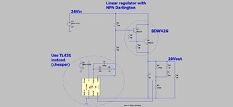
The attached (LTspice and jpeg) of a cheap, high current linear regulator, (variable voltage by divider) is not commonly seen.
Do you know why this is?
Our habitual thinking has gotten so we don't turn that often to transistor circuits. IC's have taken the stage more over the years.
Power transistors are still in the role of workhorses. It's important to know how to use transistors. However it's not that easy to collect a whole catalogue of transistor circuits in our minds, plus a list of IC's and how to use them.
Danadack's comment is a valid observation. Maybe testing/simulating under varied temperatures and input voltages and load stepping might shed light on why/why not. Not inferring, just suggesting reasons.
2N2222 is ~200 mA or so, right? , maybe ~300mW...?
With lots of simming of discrete versions of ICs and the disappointment that accompanies most forays in that direction (in my case), stability (besides psrr and temp. stuff) might turn out to be a lurking design flaw waiting to ambush the 'one set of conditions only' approach to checking a design's viability.
That said, reason may just be that some simple, useful circuits have fallen into disuse as an IC takes up less PCB space than several parts, and is cheaper.
The biggst problem I've encountered with this kind of circuit is the temptation to fit a fat capacitor at the base of the first transistor to improve ripple rejection. It does just that but if the output is momentarily shorted, the cap discharges through the base - emiiter junctions and destroys the first transistor. My experience is it usually goes fully conductive and the output voltage shoots up to almost input voltage.
This site uses cookies to help personalise content, tailor your experience and to keep you logged in if you register.
By continuing to use this site, you are consenting to our use of cookies.
") , maybe ~300mW...?
, maybe ~300mW...?