Continue to Site

Welcome to EDAboard.com

Welcome to our site! EDAboard.com is an international Electronics Discussion Forum focused on EDA software, circuits, schematics, books, theory, papers, asic, pld, 8051, DSP, Network, RF, Analog Design, PCB, Service Manuals... and a whole lot more! To participate you need to register. Registration is free. Click here to register now.

carry4 primitive simulation inconsistency

Status
Not open for further replies.

sawaak

Full Member level 2
Joined
May 20, 2003
Messages
146
Helped
4
Reputation
8
Reaction score
2
Trophy points
1,298
Activity points
1,069
Hi all,

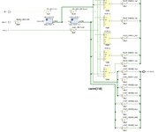
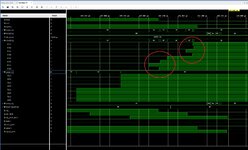
I am trying to simulate a delay line created using carry4 primitives. I am running post-synthesis timing simulation using Vivado 2021.1 and Artix-7 device. The carry4 primitive includes 4 carry logics and should have a delay associated with each of them. The problem is I am unable to observe those delays in the post-synthesis timing simulation - all carry logics associated with a particular carry4 primitive appear to have changed at the same time. I can see variable delays at the output port when I route the output to output pins which I don't want obviously when creating a TDC.

By definition, I should see the variable delays at the output of carry4 primitives (cwire[7:0] net in attached figure). Any one knows how to achieve this?

Thank you.
delay_line_sim_issue_1.jpg


delay_line_sim_issue_2.jpg
 

@sawaak
It would be very difficult to observe such delay in simulation.
Have you used the Vivado STA tools to check for the specific paths?
The tool can report the individual path delays and you can check if your desired delay is being applied or not.
 

    sawaak

    Points: 2
    Helpful Answer Positive Rating
Thank you for your comment dpaul.

It would be very difficult to observe such delay in simulation.

Even with a simulation timestep of 1ps? I am sure the delays would be bigger than that.

Have you used the Vivado STA tools to check for the specific paths?
The tool can report the individual path delays and you can check if your desired delay is being applied or not.
How to do that? Would greatly appreciate if you could give me a pointer to a relevant example.


Thank you,
sawaak
 

Even with a simulation timestep of 1ps? I am sure the delays would be bigger than that.
Analyzing/measuring signal delays from waveforms is not the correct way to proceed.

How to do that? Would greatly appreciate if you could give me a pointer to a relevant example.
You need to generate a Timing Path Report.
Read UG906 v2022.1, page 78, in which it says how would you analyze a timing path report.
In such a detailed report, you can see which path adds what amount of delay.

Read all relevant Xilinx documentations!
 

    sawaak

    Points: 2
    Helpful Answer Positive Rating
If I understand right, post#1 shows an RTL schematic. It's not necessarily implemented exactly as shown, redundant logic may be eliminated if not "frozen" by synthesis attributes. You can check the gate level schematic.
 
  • Like
Reactions: dpaul

    sawaak

    Points: 2
    Helpful Answer Positive Rating
If I understand right, post#1 shows an RTL schematic.
I do not think the OP has synthesized the design. It ilooks like a pre-synthesis netlist, commonly generated by the step "Elaborate Design" in Vivado tool.
 

You need to generate a Timing Path Report.
Read UG906 v2022.1, page 78, in which it says how would you analyze a timing path report.
In such a detailed report, you can see which path adds what amount of delay
Thank you dpaul. I will go through it and get back soon.
--- Updated ---

If I understand right, post#1 shows an RTL schematic. It's not necessarily implemented exactly as shown, redundant logic may be eliminated if not "frozen" by synthesis attributes. You can check the gate level schematic
Thank you FvM for your reply.

The schematic in post#1 was generated after synthesis and the simulation results are generated using post-synthesis timing simulation. cwire[7:0] signal was preserved using keep attribute. As far as I understood, even if the logic is removed after implementation step (need to check this), the cwire [7:0] signal is there in the synthesized netlist and should behave as per specification.

I will run implementation and get back with the results soon.
--- Updated ---

I do not think the OP has synthesized the design. It ilooks like a pre-synthesis netlist, commonly generated by the step "Elaborate Design" in Vivado tool.
I had synthesized the design and its post synthesis netlist. The elaborated netlist doesn't include IBUF, BUFG, OBUF primitives :)
--- Updated ---

I will run implementation and get back with the results soon.
I have implemented the design and the schematic looks almost identical as attached. The simulation is slightly changed with respect to post-synthesis simulation in that the delay arrangement of COUT signal is a bit different. Other than that, cwire[7:0] signal still behaves the same and as shown, is present in the post-implementation netlist and not optimized away.
 

Attachments

  • delay_line_sim_issue_1_imp_timing.jpg
    delay_line_sim_issue_1_imp_timing.jpg
    201.9 KB · Views: 134
  • delay_line_sim_issue_2_imp_timing.jpg
    delay_line_sim_issue_2_imp_timing.jpg
    637.1 KB · Views: 113
Last edited:

Hi sawaak,

Educated guess here (if I correctly understand what you´re trying to measure):
carry_4_test_0 and carry_4_test_1 have 1x input to 4x outputs which seems to have the same delay (for example, way from carry_4_test_0 output 3 => carry_4_test_1). Thus, the delay from signal_i_BUF => carry_4_test_0 output[3:0] are the same (note: the naming is confusing, out and in0 seems to be inverted? not sure), as timing from carry_4_test_1 input => carry_4_test_1 output[3:0]. These delays seems to be the same because they are generated by similar circuits (which transforms 1 input in 4 outputs).

On other hand, each output from carry_4_test_0 and carry_4_test_1 are connected to 8x individual primitives OBUF and thus, have 8 individual and different length delays.

But are you sure that carry_4_test_0 and carry_4_test_1 are really primitives? They do not look as primitives, and CARRY4 have different inputs/outputs - specially, CARRY4 should have 4x inputs. You may try to extend the carry_4_test_0 and carry_4_test_1 block and check the circuit inside.
 

Status
Not open for further replies.

Part and Inventory Search

Welcome to EDABoard.com

Sponsor

Back
Top