Audioguru
Advanced Member level 7
- Joined
- Jan 19, 2008
- Messages
- 9,457
- Helped
- 2,151
- Reputation
- 4,302
- Reaction score
- 2,008
- Trophy points
- 1,393
- Location
- Toronto area of Canada
- Activity points
- 59,721
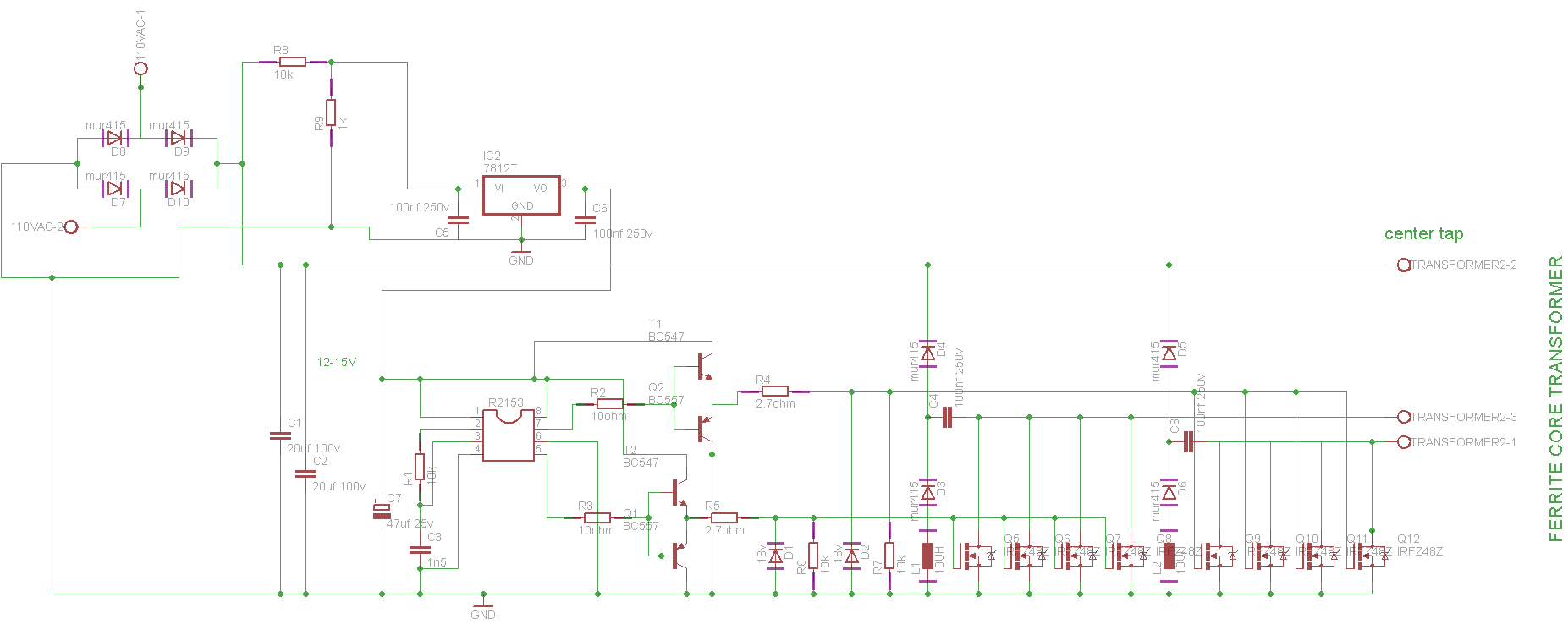
A switched mode power supply uses a high frequency (50kHz to hundreds of kHz) transformer that is fairly small and has a ferrite core.
A 12V car battery drives the high frequency oscillator that uses Mosfets to drive very high currents into the high frequency transformer then its output is rectified and filtered into the high voltage DC to feed the amplifier. Or 110VAC is rectified and filtered into 155VDC that is used to drive a high frequency oscillator that feeds a high frequency transformer then its output is rectified and filtered into the voltages needed to power the amplifier. The transformer provides isolation and changes the AC voltage to the amount that is needed.
A 12V car battery drives the high frequency oscillator that uses Mosfets to drive very high currents into the high frequency transformer then its output is rectified and filtered into the high voltage DC to feed the amplifier. Or 110VAC is rectified and filtered into 155VDC that is used to drive a high frequency oscillator that feeds a high frequency transformer then its output is rectified and filtered into the voltages needed to power the amplifier. The transformer provides isolation and changes the AC voltage to the amount that is needed.