Continue to Site

Welcome to EDAboard.com

Welcome to our site! EDAboard.com is an international Electronics Discussion Forum focused on EDA software, circuits, schematics, books, theory, papers, asic, pld, 8051, DSP, Network, RF, Analog Design, PCB, Service Manuals... and a whole lot more! To participate you need to register. Registration is free. Click here to register now.

Can I fix this Realistic Color Organ?

Status
Not open for further replies.

alexanderish

Newbie level 4
Joined
May 31, 2012
Messages
6
Helped
0
Reputation
0
Reaction score
0
Trophy points
1,281
Activity points
1,346
I broke my new toy. :( A vintage Realistic Color Organ, that basically flashed some lightbulbs in response to audio.

I tore it apart to see if I could swap out the lights, or replace the microphone with a line in. Simple enough.

Unfortunately, early on, I swapped the light and power plugs before plugging it in. There was a pop, a flash, fried electronic smell, and a broken heart.

I am not very knowledgeable about electronics. I don't know what to Google, so I hope I can get help here.

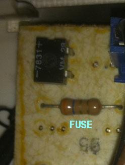
The flash of light seemed to come from the plastic and silver capacitor. On the bottom on the board, the tracks leading from the light pins(which I sent power to) were destroyed. I reconnected the broken bridges, still nothing.

Is there any hope? What part(s) exploded, and will I be able to replace them? Should I test the parts, and how?

Thanks a lot. This is a nice community!

**broken link removed**

**broken link removed**

**broken link removed**
 

Chances are that the device that drives the lights was ruined. This would be connected to the trace that melted.

Notice that the power and lights have a terminal in common. I'm guessing the black wires go to the lights.

Since the project runs on house current, it's likely the lights are controlled by a triac or scr. It looks as though it might be the rectangular chip in the corner. I cannot read its designation. (I see a number '7831' but that would be the year and week it was manufactured.)

If that chip took full house current, then I believe you need to replace it to get things working again.

I could be wrong. The triac's I've used have 3 pins and look like a medium power transistor.

It will help if you can state the number on that chip.


Device marked 7831 looks like a full diode bridge (has + and - marks). Probably the other IC is the triac (probably an optically coupled one...) marked SL27410.
 
Thanks for the response, Brad!

The chip only says VM 28, along with the 7831. It had four pins.

**broken link removed**

I was hoping it wasn't that chip that fried, but it's looking like you're right. The two melted traces led directly to it.
I've heard capacitors are easy enough to replace, but now I may need to hunt down this guy?

The other chip, I was thinking processed audio from the microphone, but I really don't know. Thanks for your input as well, Etmabreu!
 

Last edited:
Thanks for the response, Brad!

The chip only says VM 28, along with the 7831. It had four pins.

**broken link removed**

I was hoping it wasn't that chip that fried, but it's looking like you're right. The two melted traces led directly to it.
I've heard capacitors are easy enough to replace, but now I may need to hunt down this guy?

The other chip, I was thinking processed audio from the microphone, but I really don't know. Thanks for your input as well, Etmabreu!


Yes, it is a full wave rectifier. Checked the datasheet on-line. If this one is burned it is very easy to replace, even with a different part number.

---------- Post added at 20:14 ---------- Previous post was at 20:10 ----------

The other IC seems a Fairchild part (it even has the "F" mark) but I can't find the datasheet (probably a long ago obsolete part).
 
Feeling better! Thanks, everyone. I'm thinking about ordering this guy, which I've gathered is the same as **broken link removed**.
 

As Etmabreu's post states, the + and - signs are typically seen on a bridge rectifier.

And that is what VM28 turns up as on Google.

It occurred to me that it would be part of the power supply, but then the connected traces should not have melted when power was connected.

On the other hand, if it was part of the power output stage, it is non-typical use of a diode bridge.

If it is a bridge rectifier then a replacement will not be hard to find. It must match pin for pin. The + and - must be at the same spot.

All the better if you can test each diode inside the one that is on the board. Ordinarily this will require disconnecting at least 3 pins from the board. You might find a way to do this by cutting through your repaired traces.

Radio Shack will probably have a replacement. This is a common chip.
 
Just checking in. Thank you everybody for your help. I couldn't find a proper replacement at the phone store that is Radioshack, so I went ahead and internetted it. I'm hoping that once my part comes, it will be dandy.

If not, I will consider that board sadly deceased. ALERTLINKS, and some further hunting led me to believe that constructing a Color Organ isn't that complicated, and should be fun. Already ordered kits and parts for my next project!

I said that I thought this was a neat community. You guys proved it. I think of myself as a big nerd in a lot of subjects, but really dumfounded in electronics. I see myself keeping an eye on this place as I venture into future projects. Thank you~
 

The diode bridge and small transistor shaped scr are most likely damaged.

After installing a new diode bridge, it still didn't work. Did a basic multimeter test on everything. The only bug was that 'transistor shaped scr'. Googling didn't really help me with that. Where do you suppose I might find a replacement?

Thanks!
 

1.

Did you check for volt level at a few components?

2.

Can you verify that your repairs to the trace/traces has now restored very low resistance between the components it connects?

3.

It looks as though the VM28 is sitting on a socket. Is that the case? The fragile contacts might have gotten scorched. Can you verify that AC power is getting to the AC pins of the VM28? And that DC is going out from the plus+ and minus- pins?
 

Okay, update. I replaced that "resistor shaped scr" with a super low resistor (the stripes on the component spelled out 3.6 ohms) and now have lights. But the lights are static. That kind of makes sense, based on what I've learned about SCR's.

Brad,

1. Using a multimeter, I checked every component. The only one that seemed off was that Resistor Shaped SCR, which seemed to be busted, as there was no flow through it.

2. I've tested my repair traces, and there doesn't seem to be any resistance.

3. No socket, just embedded into the board. Replaced the chip, and the contacts seem to be legit. With the lights working, I would assume that the power is going though.

Thanks, again.

- - - Updated - - -

Okay, update. I replaced that "resistor shaped scr" with a super low resistor (the stripes on the component spelled out 3.6 ohms) and now have lights. But the lights are static. That kind of makes sense, based on what I've learned about SCR's.

Brad,

1. Using a multimeter, I checked every component. The only one that seemed off was that Resistor Shaped SCR, which seemed to be busted, as there was no flow through it.

2. I've tested my repair traces, and there doesn't seem to be any resistance.

3. No socket, just embedded into the board. Replaced the chip, and the contacts seem to be legit. With the lights working, I would assume that the power is going though.


So basically. I'm left wondering about this Resistor Shaped SCR. I can't find any info about such a device. All the SCR's I've read about have three terminals and are black and silver chips.

Thanks, again.
 

Regarding the "transistor shaped thing", had it any readable marks on it?

All the SCRs have three terminals. _IF_ that thing is really an SCR, probably you could manage to fit anything else there, like a BT137. It is probably "overkill", but it would work.
 

Can you show board pic with 'wires with connector' removed. Some parts below these wires can't be seen in the pic you posted.

If you'r talking about this resister, its actually a fuse.
37_1339768435.jpg

If its found blown, you can bridge solder with a thin wire between two points on pcb tracks side.
 

The fact that you have made the lights come on is progress.

Since they stay on, it means you still need to track down the scr/triac, because that is probably what makes them turn on and off. Right now it is failed as a short.

It would be a component with either 3 pins (possibly the transistor-like piece near the silvery capacitor)...

or 4 pins (if it is an optocoupler type).

I could be wrong.
 

Status
Not open for further replies.

Part and Inventory Search

Welcome to EDABoard.com

Sponsor

Back
Top