gautamraavi
Newbie level 5
I am trying for an ac dc boost converter.
i am getting the following error in transient analaysis
Analysis `tran' was terminated prematurely due to an error.
finalTimeOP: writing operating point information to rawfile.
modelParameter: writing model parameter values to rawfile.
element: writing instance parameter values to rawfile.
outputParameter: writing output parameter values to rawfile.
designParamVals: writing netlist parameters to rawfile.
primitives: writing primitives to rawfile.
subckts: writing subcircuits to rawfile.
*************************************************
Transient Analysis `tran': time = (0 s -> 500 us)
*************************************************
Important parameter values:
start = 0 s
outputstart = 0 s
stop = 500 us
step = 500 ns
maxstep = 5 us
ic = all
skipdc = no
reltol = 100e-06
abstol(V) = 1 uV
abstol(I) = 1 pA
temp = 27 C
tnom = 27 C
tempeffects = all
errpreset = conservative
method = gear2only
lteratio = 10
relref = alllocal
cmin = 0 F
gmin = 1 pS
Error found by spectre at time = 20e-21 s during transient analysis `tran'.
ERROR (SPECTRE-16192): No convergence achieved with the minimum time step specified. Last acceptable solution computed at 0 s.
The values for those nodes that did not converge on the last Newton iteration are given below. The manner in which the convergence criteria were not satisfied is also given.
Failed test: | Value | > RelTol*Ref + AbsTol
Top 9 Residue too large Convergence failure:
V(net07) = -154.965e-21 V, previously 0 V.
residue too large: | 170.462 uA | > 17.0462 nA + 1 pA
The following set of suggestions might help you avoid convergence difficulties.
1. Evaluate and resolve any notice, warning, or error messages.
2. Use realistic device models. Check all component parameters, particularly nonlinear device model parameters, to ensure that they are reasonable.
3. Small floating resistors connected to high impedance nodes might cause convergence difficulties. Avoid very small floating resistors, particularly small parasitic resistors in semiconductors. Instead, use voltage sources or iprobes to measure current.
4. Ensure that a complete set of parasitic capacitors is used on nonlinear devices to avoid jumps in the solution waveforms. On MOS models, specify nonzero source and drain areas.
5. Perform sanity check on the parameter values using the parameter range checker (use ``+param param-limits-file'' as a command line argument) and heed any warnings. Print the minimum and maximum parameter value using the `info' analysis. Ensure that the bounds given for instance, model, output, temperature-dependent, and operating-point (if possible) parameters are reasonable.
6. Check the direction of both independent and dependent current sources. Convergence problems might result if current sources are connected such that they force current backward through diodes.
7. Enable diagnostic messages by setting option `diagnose=yes'.
8. Use the `cmin' parameter to install a small capacitor from every node in the circuit to ground. This usually eliminates any jumps in the solution.
9. Loosen tolerances, particularly absolute tolerances like `iabstol' (on options statement). If tolerances are set too tight, they might preclude convergence.
10. Try to simplify the nonlinear component models in order to avoid regions in the model that might contribute to convergence problems.
---------- Post added at 01:28 ---------- Previous post was at 01:27 ----------

image of my circuit
i am getting the following error in transient analaysis
Analysis `tran' was terminated prematurely due to an error.
finalTimeOP: writing operating point information to rawfile.
modelParameter: writing model parameter values to rawfile.
element: writing instance parameter values to rawfile.
outputParameter: writing output parameter values to rawfile.
designParamVals: writing netlist parameters to rawfile.
primitives: writing primitives to rawfile.
subckts: writing subcircuits to rawfile.
*************************************************
Transient Analysis `tran': time = (0 s -> 500 us)
*************************************************
Important parameter values:
start = 0 s
outputstart = 0 s
stop = 500 us
step = 500 ns
maxstep = 5 us
ic = all
skipdc = no
reltol = 100e-06
abstol(V) = 1 uV
abstol(I) = 1 pA
temp = 27 C
tnom = 27 C
tempeffects = all
errpreset = conservative
method = gear2only
lteratio = 10
relref = alllocal
cmin = 0 F
gmin = 1 pS
Error found by spectre at time = 20e-21 s during transient analysis `tran'.
ERROR (SPECTRE-16192): No convergence achieved with the minimum time step specified. Last acceptable solution computed at 0 s.
The values for those nodes that did not converge on the last Newton iteration are given below. The manner in which the convergence criteria were not satisfied is also given.
Failed test: | Value | > RelTol*Ref + AbsTol
Top 9 Residue too large Convergence failure:
V(net07) = -154.965e-21 V, previously 0 V.
residue too large: | 170.462 uA | > 17.0462 nA + 1 pA
The following set of suggestions might help you avoid convergence difficulties.
1. Evaluate and resolve any notice, warning, or error messages.
2. Use realistic device models. Check all component parameters, particularly nonlinear device model parameters, to ensure that they are reasonable.
3. Small floating resistors connected to high impedance nodes might cause convergence difficulties. Avoid very small floating resistors, particularly small parasitic resistors in semiconductors. Instead, use voltage sources or iprobes to measure current.
4. Ensure that a complete set of parasitic capacitors is used on nonlinear devices to avoid jumps in the solution waveforms. On MOS models, specify nonzero source and drain areas.
5. Perform sanity check on the parameter values using the parameter range checker (use ``+param param-limits-file'' as a command line argument) and heed any warnings. Print the minimum and maximum parameter value using the `info' analysis. Ensure that the bounds given for instance, model, output, temperature-dependent, and operating-point (if possible) parameters are reasonable.
6. Check the direction of both independent and dependent current sources. Convergence problems might result if current sources are connected such that they force current backward through diodes.
7. Enable diagnostic messages by setting option `diagnose=yes'.
8. Use the `cmin' parameter to install a small capacitor from every node in the circuit to ground. This usually eliminates any jumps in the solution.
9. Loosen tolerances, particularly absolute tolerances like `iabstol' (on options statement). If tolerances are set too tight, they might preclude convergence.
10. Try to simplify the nonlinear component models in order to avoid regions in the model that might contribute to convergence problems.
---------- Post added at 01:28 ---------- Previous post was at 01:27 ----------
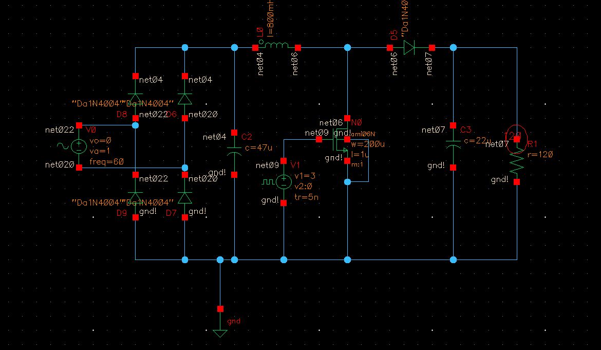
image of my circuit