SeriousTyro
Member level 2
Hi,
I'm looking to build a 3input XOR gate that minimizes EDP.
I've been looking through web and found some some enticing designs:
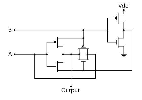
from wikipedia
**broken link removed**
from
**broken link removed**
https://ieeexplore.ieee.org/stamp/stamp.jsp?tp=&arnumber=824054&userType=&tag=1
They all use 12 transistors so it is hard to tell which one is the "best".
I'm using the XOR for a full adder which is to be implemented into a 32 bit ALU.
I was wondering which one of these is the "best" ?
In my digital design class, we've always talking about nands, nors, and inverters.
An AND Gate can be made using a NAND and Inverter but this seems like a extraneous use of transistors.
Is there another way of making an AND gate? Similarly OR?
I'm looking to build a 3input XOR gate that minimizes EDP.
I've been looking through web and found some some enticing designs:
from wikipedia
**broken link removed**
from
**broken link removed**
https://ieeexplore.ieee.org/stamp/stamp.jsp?tp=&arnumber=824054&userType=&tag=1
They all use 12 transistors so it is hard to tell which one is the "best".
I'm using the XOR for a full adder which is to be implemented into a 32 bit ALU.
I was wondering which one of these is the "best" ?
In my digital design class, we've always talking about nands, nors, and inverters.
An AND Gate can be made using a NAND and Inverter but this seems like a extraneous use of transistors.
Is there another way of making an AND gate? Similarly OR?